Screen module for vibratory screening apparatus

a technology of vibratory screening and screen module, which is applied in the direction of screening, solid separation, sieving, etc., to achieve the effect of reducing the flex of the screen panel, and facilitating a degree of flex

Active Publication Date: 2012-03-06
F L SMIDTH & CO AS
View PDF18 Cites 43 Cited by
  • Summary
  • Abstract
  • Description
  • Claims
  • Application Information

AI Technical Summary

Benefits of technology

[0010]The invention advantageously provides an alternative screen module for vibratory screening apparatus. In certain embodiments the module advantageously alleviates excessive flex of the screen panel, while facilitating a degree of flex desired for a particular application without resulting in excessive wear of the screen panel. Also, in certain embodiments the module advantageously facilitates easy assembly of the module on the apparatus and economical replacement of wearing parts.
[0022]If a sub-frame is included in the panel frame, each of the screen panels preferably includes a complementary web adapted to overlie a respective sub-frame portion. For example, if each panel portion of the panel frame includes a cruciform sub-frame, each screen panel preferably includes a complementary cruciform web. In such cases, the sub-frame portions are preferably provided with engagement formations and the webs of the screen panels are provided with complementary engagement portions. Preferably, the engagement formations of the sub-frame portions and the webs of the screen panels have a continuous or discontinuous clip-in profile that facilitates clipping of the webs of the screen panels to the sub-frame portions.
[0026]The panel frame itself is engaged onto the panel support rails which are conventionally attached onto the structural members of the vibratory screening apparatus. The panel support rails provide two main functions. One is to hold down the frame, which is simply knocked onto the panel support rails and is preferably held in place by double edge taper end faces. The other is to provide an abutment, and final peripheral support, for neighbouring support frames, thereby providing a continuous and flush screen surface without the need for lock down bars as seen in the prior art. The support frame itself may be fully located onto the panel support rails via alignment lugs and it may be easily removed from the panel support rails via pry slots. It is expected that the panel frame will significantly outlast the screen panel. The invention therefore advantageously maximises replacement efficiency and reduces down time on site.
[0027]As mentioned above, the panel frame preferably includes a sub-frame, in which case the screen panels preferably include complementary webs that may be associated with, or engaged with, the sub-frame. Such an arrangement has been found to provide substantial advantages in that the sub-frame, and the engagement of the webs with the sub-frame provide added support and strength to the screen panel during operation.

Problems solved by technology

However, in particular applications the screen panels may be blank or contain no screening apertures.

Method used


Image

  • Screen module for vibratory screening apparatus
  • Screen module for vibratory screening apparatus
  • Screen module for vibratory screening apparatus

Examples


Embodiment Construction

[0042]More detailed embodiments of the invention will now be described with reference to the accompanying drawings. This description is provided for reference only and should not be construed as limiting on the invention in any way. Referring to the accompanying drawings:

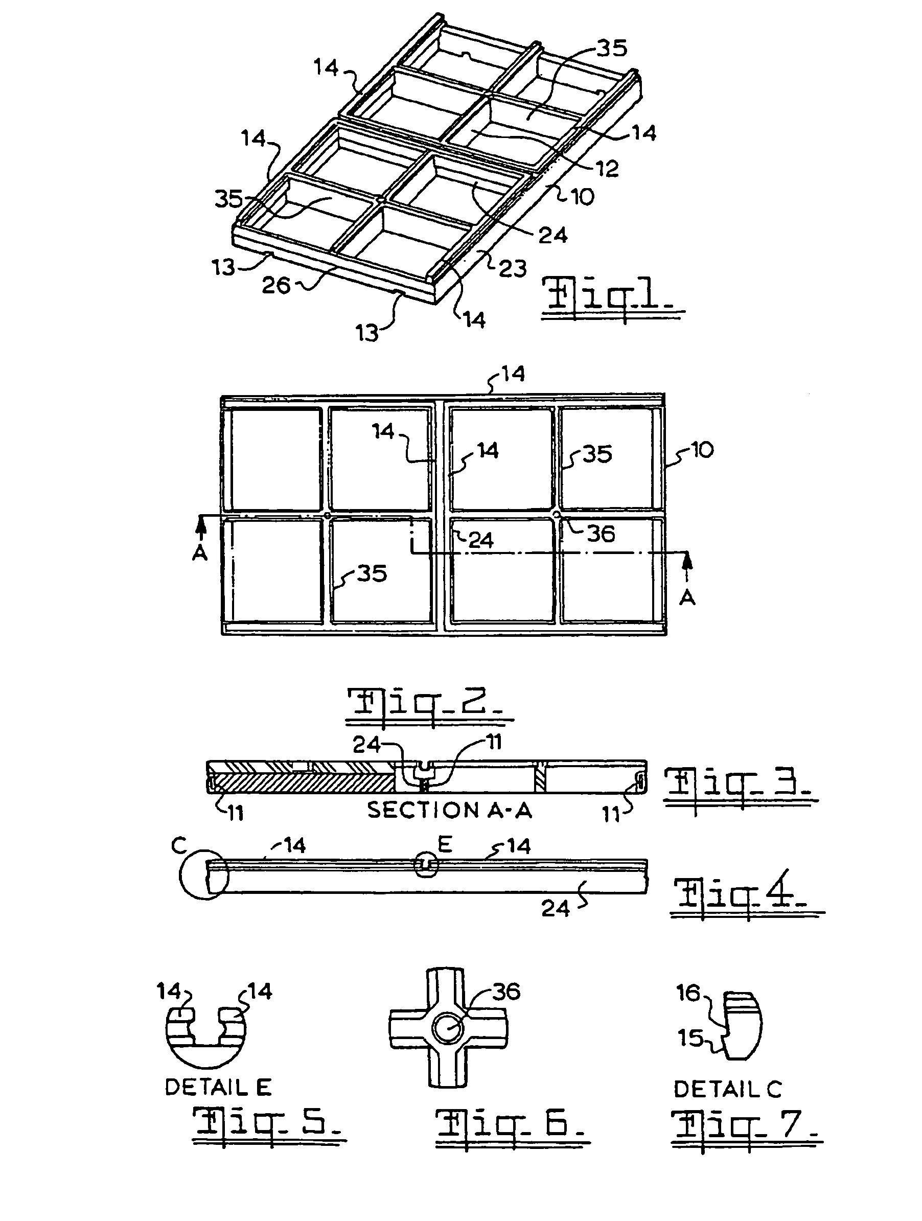
[0043]FIG. 1 is a perspective view of a panel frame;

[0044]FIG. 2 is a plan view of the panel frame of FIG. 1;

[0045]FIG. 3 is a section A-A through the panel frame of FIG. 2;

[0046]FIG. 4 is a side view of the panel frame of FIG. 1;

[0047]FIG. 5 is a detail view of the centre section of the panel frame of FIG. 4;

[0048]FIG. 6 is a detail view of the centre of sub-frame of the panel frame shown in FIG. 2;

[0049]FIG. 7 is a detail view of the end profile of the panel frame of FIG. 4;

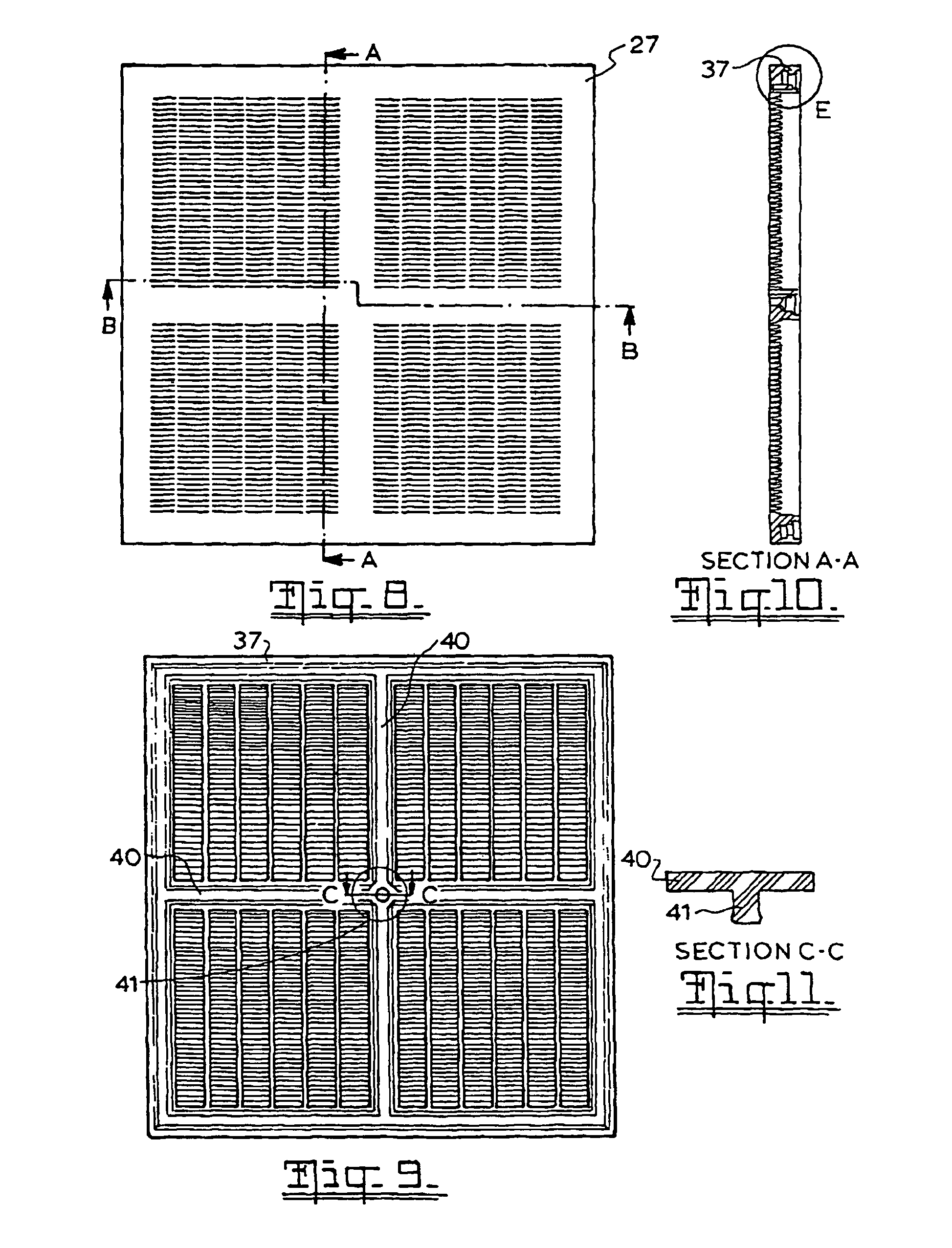
[0050]FIG. 8 is a top plan view of a screen panel suitable for use on the panel frame of FIG. 1;

[0051]FIG. 9 is a is a bottom plan view of the screen panel of FIG. 8;

[0052]FIG. 10 is a section A-A through the screen panel of FIG. 8;

[0053]FIG. 1...


PUM


Abstract

The invention provides a screen module for use on vibratory screening apparatus. The screen module includes: a panel frame having opposed side portions joined by opposed end portions, the end portions being configured for locating the panel frame between spaced panel support rails of the vibratory screening apparatus; at least one intermediate portion extending between the opposed side portions and / or opposed end portions and dividing the panel frame into panel portions; the side portions and said at least one intermediate portion having engagement formations provided on upper surfaces thereof that, together with engagement formations provided on each of the panel support rails of the vibratory screening apparatus, in use, form peripheral panel engagement formations about the panel portions; and at least one pair of screen panels, said screen panels overlying respective panel portions of the panel frame and including complementary engagement formations on an underside periphery thereof for engagement with the peripheral panel engagement formations, defined by the engagement formations of the panel frame and panel support rails.

Description

FIELD OF THE INVENTION[0001]The present invention relates to a screen module for vibratory screening apparatus. In particular, the invention relates to screen modules including a frame and removable screening panels for vibratory screening apparatus, and screening panels for use in such modules.BACKGROUND TO THE INVENTION[0002]In the art of vibratory screening apparatus, there are advantages in the use of polymeric screening members. Certain polymers, such as polyurethanes, may be used in lieu of fabricated metal screens in cases where the superior resistance to abrasive wear possessed of polyurethane is an advantage. Polyurethane screening members may be moulded in a wide variety of forms with ease, as opposed to the limitations in fabricating metal screens. Most polyurethane screening members incorporate edge and intermediate reinforcing of steel or other reinforcing to rigidly support the screen surface thereon.[0003]Screening panels may be monolithic, where the screening surface...

Claims


Application Information

Patent Timeline
Patent Type & Authority Patents(United States)
IPC IPC(8): B07B1/46
CPCB07B1/4645
Inventor TRENCH, MICHAELBIRTASEVIC, SASHAGRUEVSKI, GEORGETHEKKUVEETIL, KISHOR RAVI
Owner F L SMIDTH & CO AS
Why Eureka
Try Eureka