Metering dispensing system with one-piece pump assembly

a pump assembly and metering technology, applied in the direction of instruments, liquid handling, single-unit apparatuses, etc., can solve the problems of erratic fluid volume, valve opening, and more fluid material to be deposited

Active Publication Date: 2012-03-13
1TOUCH HLDG INC
View PDF115 Cites 13 Cited by
  • Summary
  • Abstract
  • Description
  • Claims
  • Application Information

AI Technical Summary

Benefits of technology

[0014]As shown in the appended Figures, an upstanding circumferential wall is positioned about the dome button to prevent unwanted actuation thereof. The wall is preferably integrally molded with the dome button and the top portion extension. The wall is preferably relatively rigid and is not easily compressed when pressure is placed generally across it. Thus, to actuate the dome button for pumping, the flexible dome button itself must be specifically depressed, such as by a user's finger. As a result, actuation of the pump assembly is more likely to be carried out only when specifically desired. The integrated formation of parts makes the manufacture easier and less costly while retaining if not improving performance because there are less welds in the finished assembly.
[0025]Another object of the present invention to provide an exterior metering dispensing system that has a number of components integrally formed to better incorporate the pump assembly into a given application and simplify manufacturing and assembly of the container onto which it is installed.

Problems solved by technology

While this method has provided marginally acceptable results, this method also typically yields an erratic fluid volume since more or less fluid material may be delivered on each successive squeeze of the container body.
The difficulty here is that the valve over time becomes partially clogged thereby requiring that the user apply additional pressure to cause the valve to open.
As a result, once the valve opens, the additional pressure causes more fluid material to be deposited than the user typically would have desired.

Method used


Image

  • Metering dispensing system with one-piece pump assembly
  • Metering dispensing system with one-piece pump assembly
  • Metering dispensing system with one-piece pump assembly

Examples


Embodiment Construction

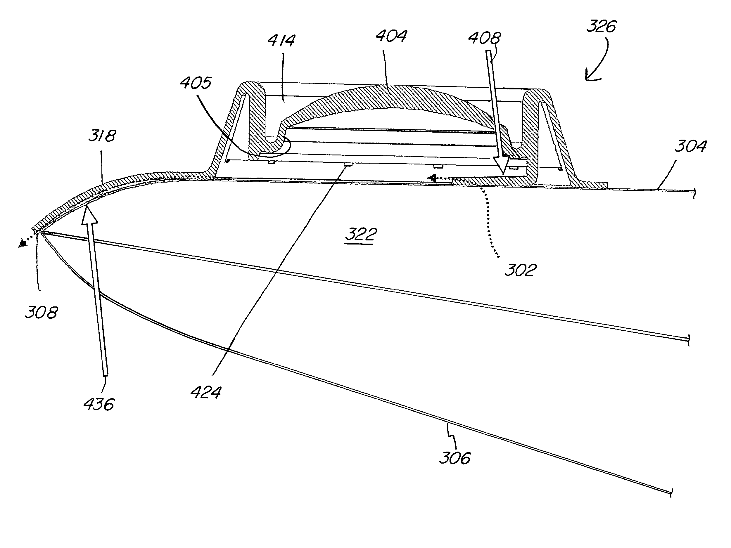
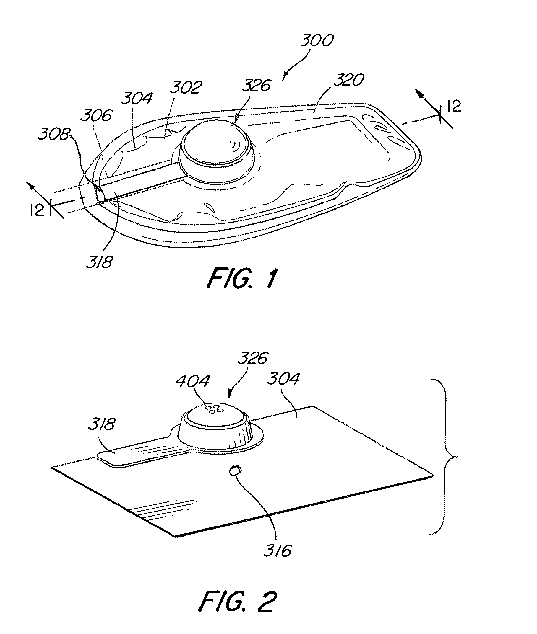
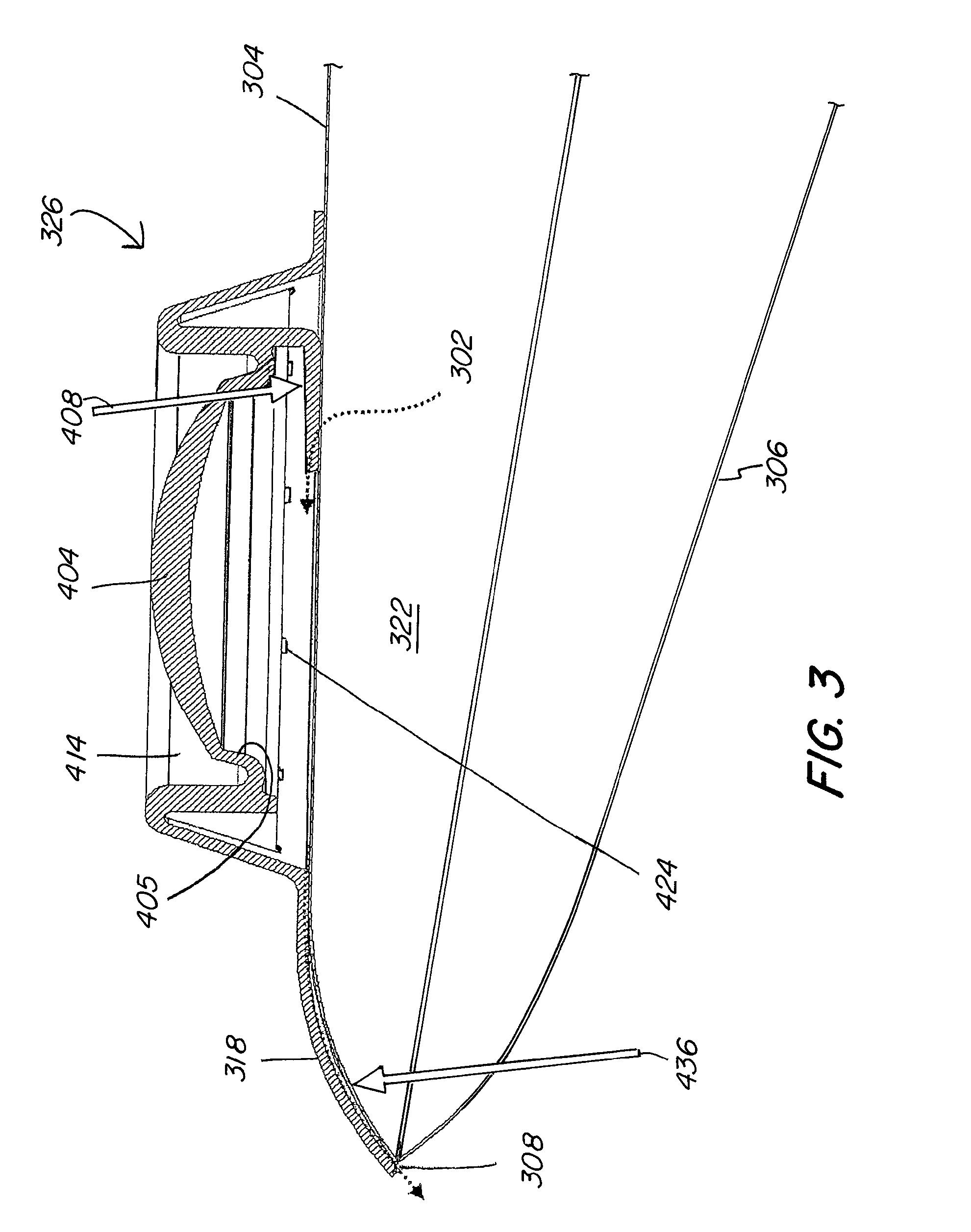
[0034]Turning now to FIGS. 1-4, details are shown of a device 300 that includes the improved dispensing device of the present invention that prevents inadvertent or accidental dispensing of liquid 302 even when pressure is placed on the dome button 404 or storage container 320. An efficient method of manufacturing a quality dispensing device 300 is to employ heat welding to construct the container 320. For example, a top sheet 304 is typically heat welded to a bottom sheet 306 about their periphery to form a container 320 with an interior fluid storage region 322 therein. Other types of bonding, e.g. adhesive, are also contemplated.

[0035]The term weld, as used herein, is meant to include seal, adhere, bond, etc. Welding may be accomplished by heat, vibration, chemical, adhesive, ultrasonic or any other means of joining polymers known to those of ordinary skill in the art.

[0036]The term seal, as used herein, may be accomplished by pressure, heat, vibration, chemical, adhesive, ultras...


PUM


Abstract

A liquid dispensing device includes a storage container having an opening and dome pump assembly attached thereto substantially over the opening for metered dispensing. The dome pump assembly is integrally formed with a dome button, top portion extension and valve to facilitate manufacture and reduce costs of the pump while improving performance thereof. The valve is employed to pull liquid from the storage container into the dome for metering. An exit passageway formed from the extension and container wall serves as an output valve. The user squeezes the dome and the opposite side of the container pouch concurrently to seal the flapper valve to urge liquid out through the exit passageway for actual dispensing.

Description

CROSS-REFERENCE TO RELATED APPLICATIONS[0001]This application is a continuation of U.S. patent application Ser. No. 12 / 832,798, filed Jul. 8, 2010, now abandoned which claims the benefit under 35 U.S.C. §119 (e) of the U.S. Provisional Patent Application Ser. No. 61 / 223,883, filed on Jul. 8, 2009. The application Ser. No. 12 / 832,798 is also a continuation-in-part of U.S. patent application Ser. No. 12 / 052,338, filed Mar. 20, 2008, now U.S. Pat. No. 8,061,566 which in turn is a continuation-in-part of U.S. patent application Ser. No. 11 / 951,351, filed Dec. 6, 2007, now U.S. Pat. No. 7,997,454 which application claims the benefit under 35 U.S.C. §119 (e) of the U.S. Provisional Patent Application Ser. No. 60 / 914,243, filed Apr. 26, 2007. The application Ser. No. 12 / 832,798 is also a continuation-in-part of U.S. patent application Ser. No. 11 / 074,817, filed Mar. 8, 2005, now U.S. Pat. No. 7,419,322, issued Sep. 2, 2008, which in turn claims the benefit under 35 U.S.C. §119 (e) of the U...

Claims


Application Information

Patent Timeline
Patent Type & Authority Patents(United States)
IPC IPC(8): B65D37/00
CPCB05C17/00569B05C17/00583B05B11/026B05B11/1032B05B11/1033
Inventor MILETI, ROBERT J.
Owner 1TOUCH HLDG INC
Why Eureka
Try Eureka