Flow plug with length-to-hole size uniformity for use in flow conditioning and flow metering

a technology of flow plugs and plug holes, applied in the direction of instruments, volume metering, liquid/fluent solid measurement, etc., can solve the problems of large variation in permanent pressure loss, type of flow disruption, and permanent pressure loss

Active Publication Date: 2012-03-13
NASA
View PDF3 Cites 38 Cited by
  • Summary
  • Abstract
  • Description
  • Claims
  • Application Information

AI Technical Summary

Benefits of technology

[0010]Still another object of the present invention is to provide a flow plug that conditions a fluid flow in a way that a coefficient of discharge, permanent pressure losses, and vena contracta can be optimized.

Problems solved by technology

However, this often requires some type of disruption of the flow where the flow measurement instrumentation (e.g., pitot tubes, spinning fans, etc.) is positioned.
However, in such cases, permanent pressure loss varies widely depending on the pattern of holes.
These conditions yield permanent pressure losses and yield less than optimal confidence in the flow measurement results generated by such flow meters.

Method used


Image

  • Flow plug with length-to-hole size uniformity for use in flow conditioning and flow metering
  • Flow plug with length-to-hole size uniformity for use in flow conditioning and flow metering
  • Flow plug with length-to-hole size uniformity for use in flow conditioning and flow metering

Examples


Embodiment Construction

)

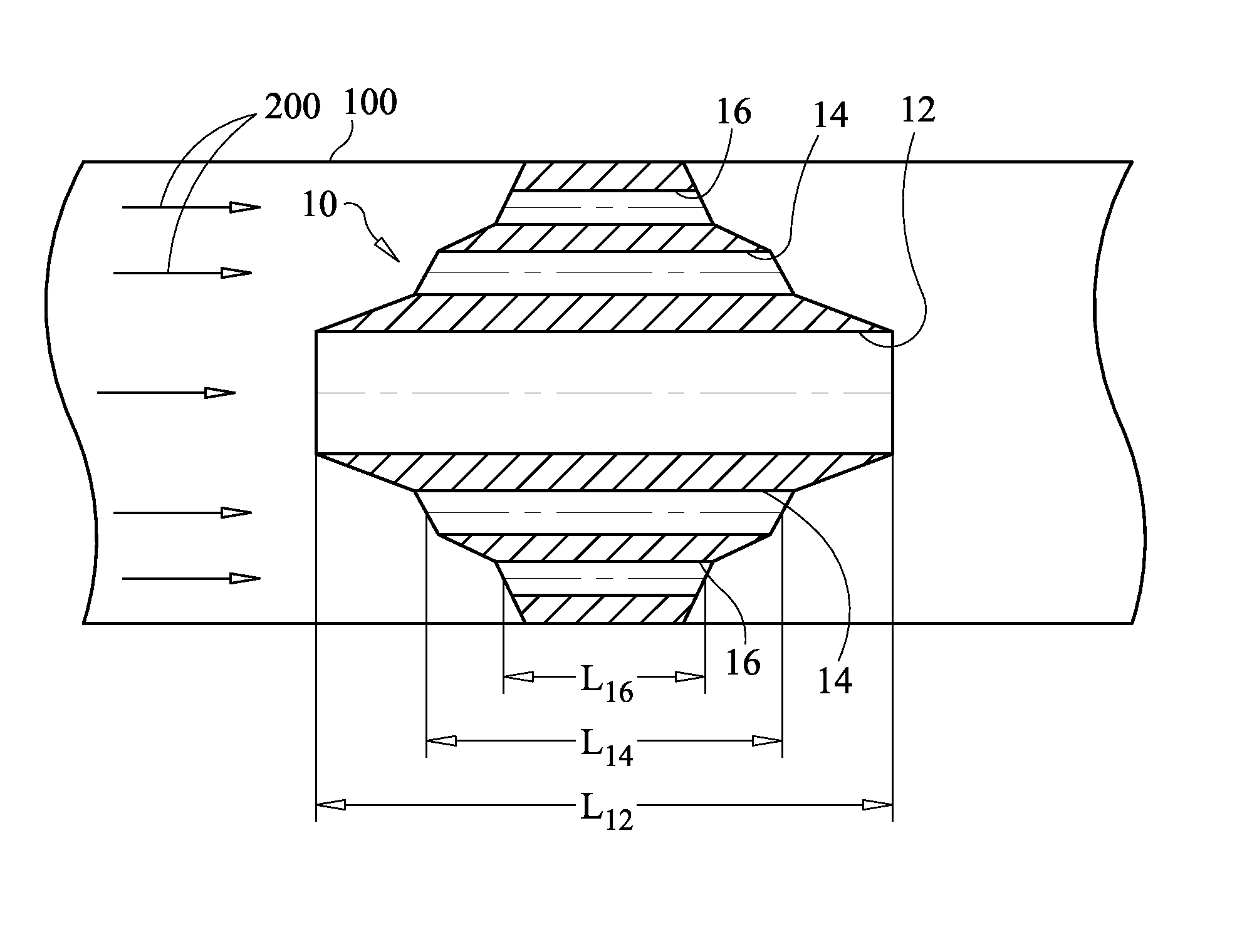
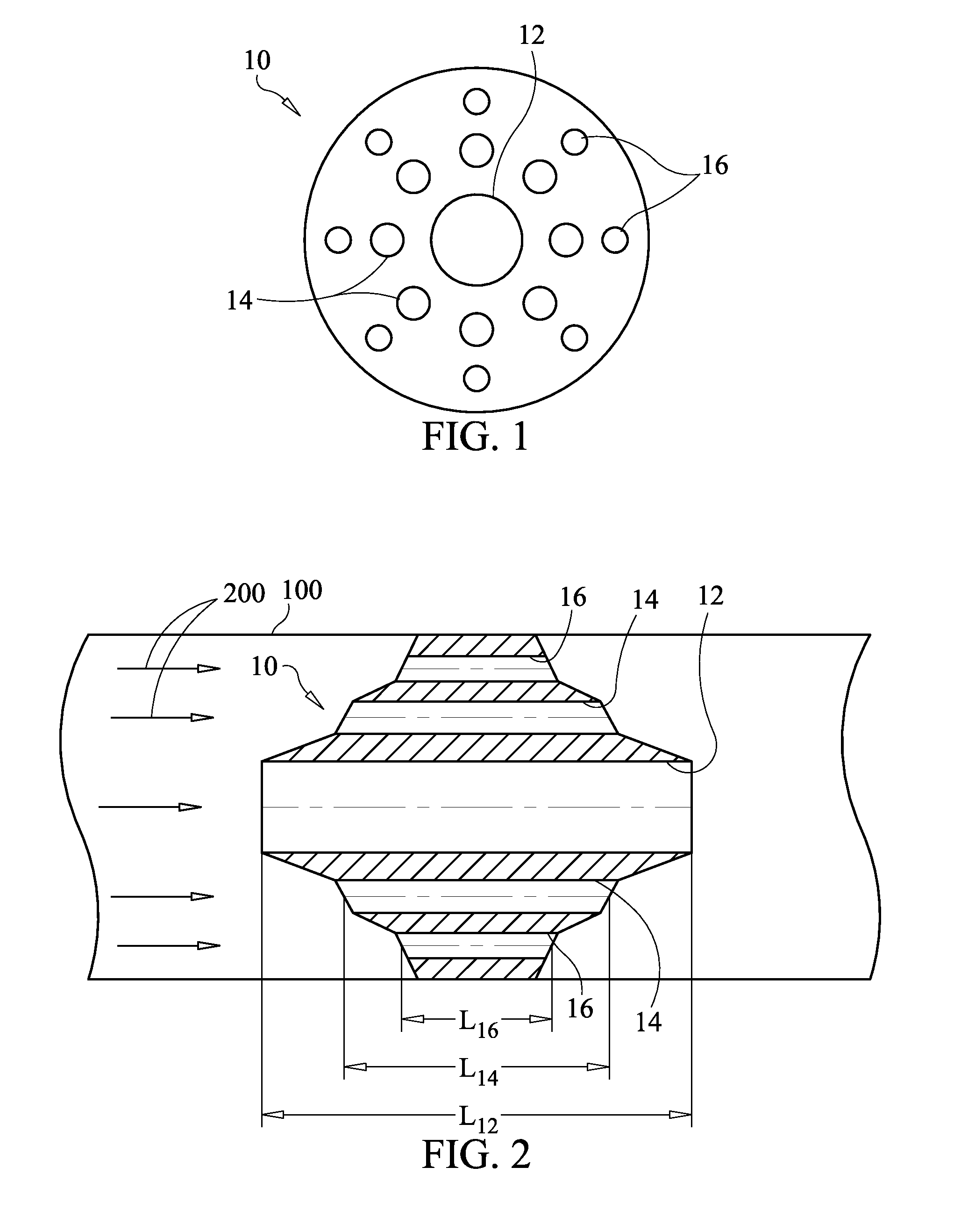
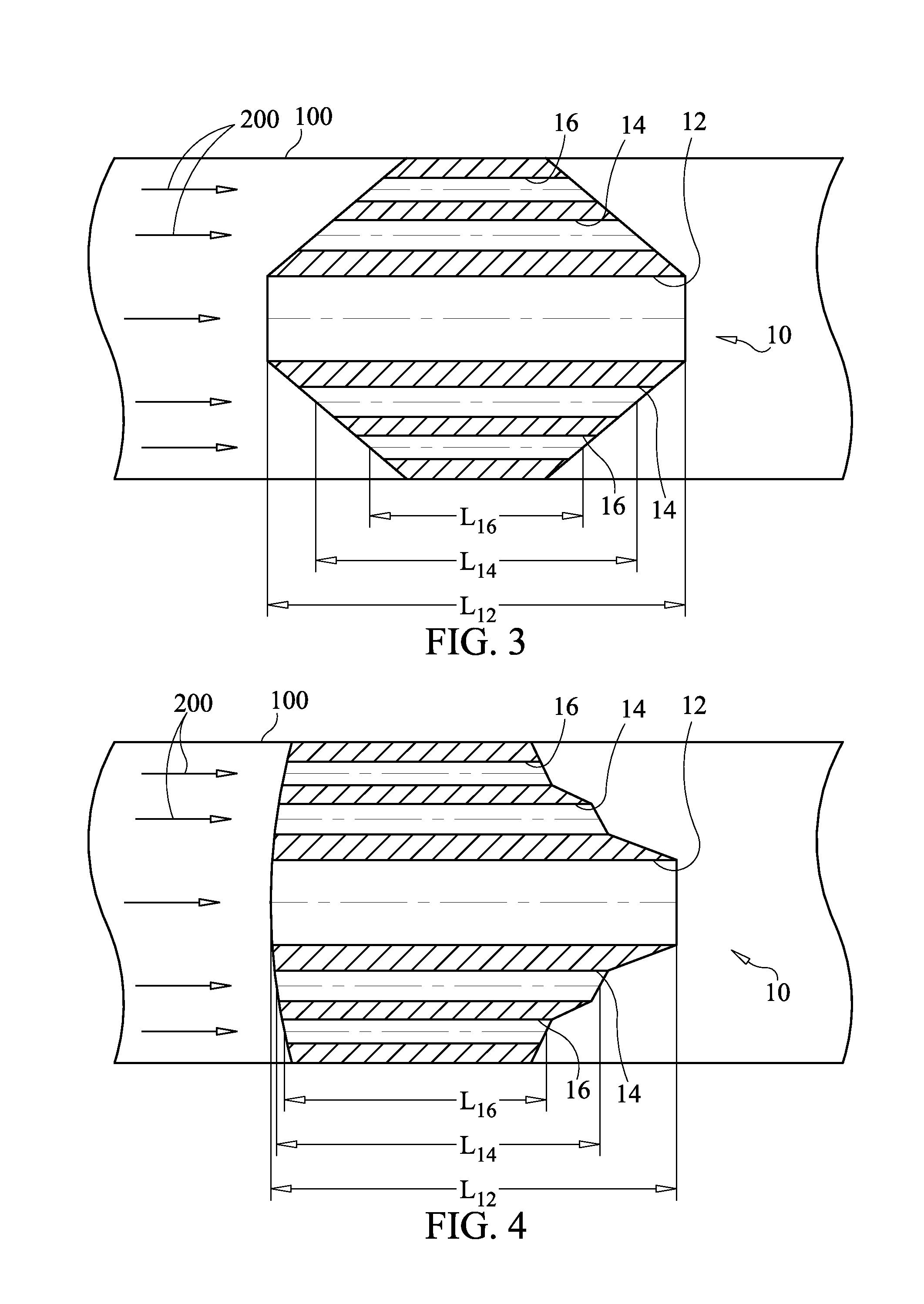
[0024]The present invention is a flow plug that can be used to condition a flow and / or be used in the measurement of process variables associated with a flow. The flow plug improves constrained fluid flow measurements by (i) producing a more uniform vena contracta for a flow that has been interrupted for measurement purposes, and (ii) being capable of having the plug's coefficient of discharge and efficiency clearly optimized. This improves flow measurement capability while minimizing pressure loss. In general, the flow plug has holes formed therethrough with the plug being installed in a fluid-carrying conduit such that the fluid passes through the plug's holes. All fluid flowing through conduit must pass through the plug's holes. As used herein, the term “plug” includes any structural element that satisfies the constraints that will be described herein. The flow plug can be used to condition a fluid flow such that flow measurements upstream and / or downstream of the plug are facil...


PUM


Abstract

A flow plug of varying thickness has a plurality of holes formed therethrough. The plug fits in a conduit such that a fluid flow in the conduit passes through the plug's holes. Each hole is defined by a parameter indicative of size in terms of the cross-sectional area thereof. A ratio of hole length-to-parameter is approximately the same for all of the holes.

Description

ORIGIN OF THE INVENTION[0001]The invention was made by employees of the United States Government and may be manufactured and used by or for the Government for governmental purposes without the payment of any royalties.BACKGROUND OF THE INVENTION[0002]1. Field of the Invention[0003]This invention relates to flow conditioners and flow meters. More specifically, the invention is a flow plug whose holes exhibit a length-to-size uniformity.[0004]2. Description of the Related Art[0005]There are numerous applications utilizing fluid flow in a conduit where a flow must be conditioned or one or more process variables associated with a fluid flow (e.g., pressure, temperature, mass flow, etc.) must be measured. “Flow conditioners” include simple orifice plates. To measure a variety of flow process variables, a variety of “flow meters” have been developed. Flow meters having no moving parts or power requirements are preferred.[0006]Some flow meters include an orifice plate disposed in a fluid f...

Claims


Application Information

Patent Timeline
Patent Type & Authority Patents(United States)
IPC IPC(8): B01F5/06
CPCB01F5/0428F15D1/001G01F1/36G01F15/00B01F25/31242
Inventor ENGLAND, JOHN DWIGHTKELLEY, ANTHONY R.
Owner NASA
Why Eureka
Try Eureka