Pole mounting device

a technology for mounting devices and poles, which is applied in the direction of lighting support devices, candle holders, religious equipment, etc., can solve the problems of limiting the ability of spotters to assist skiers, limiting the mounting locations, and limiting the mounting positions of flag holders

Active Publication Date: 2012-03-27
BUCHNER MICHAEL R
View PDF30 Cites 34 Cited by
  • Summary
  • Abstract
  • Description
  • Claims
  • Application Information

AI Technical Summary

Benefits of technology

[0006]A pole mounting device includes a holder portion, a support portion, and a clamp. The holder portion is generally tubular and hollow with an interior surface. A part of the interior surface at one end of the holder portion is shaped to form a pole cavity sized to receive the lower end of a pole. A part of the interior surface at the other end of the holder portion is shaped to form a ball socket. A side window extends through the holder portion into the ball socket. The support portion has an elongated cylindrical rod and a ball with a larger diameter than the rod section attached to one end of the rod. The ball is sized to fit into the ball socket to form a ball joint, with the rod extending outwardly through the window. A means for adjusting the holding force of the ball joint connects to the holder portion. The clamp attaches to the rod opposite the ball. The ball joint allows the holder portion to rotate relative to the support portion about a first axis through the center of the rod and about a second axis transverse to the first axis. An adapter with a short pole permits mounting of mobile electronic devices.

Problems solved by technology

Holding the flag can limit the ability of the spotter to aid the skier or do other tasks.
Generally these flag holders must be mounted on a vertical surface, limiting the possible mounting locations.
Possible obstruction by boat structures further limits the mounting positions of these flag holders.

Method used


Image

  • Pole mounting device
  • Pole mounting device
  • Pole mounting device

Examples


Embodiment Construction

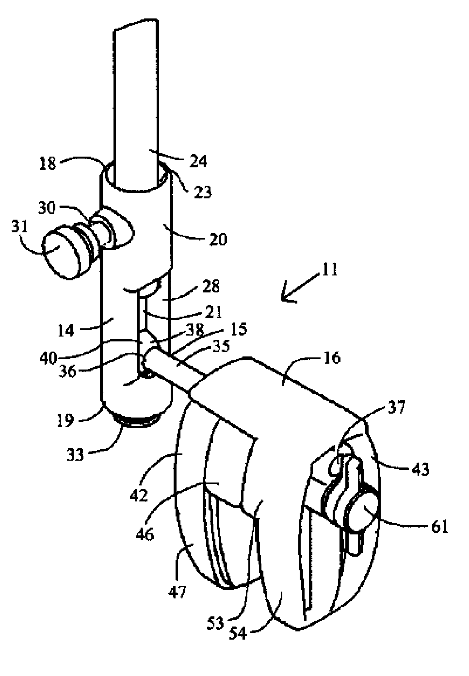
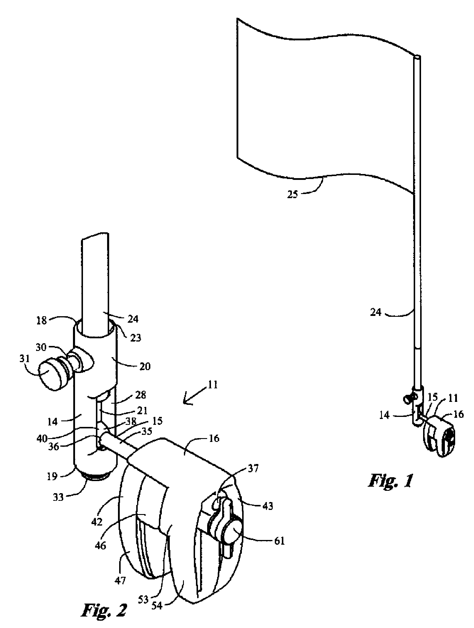
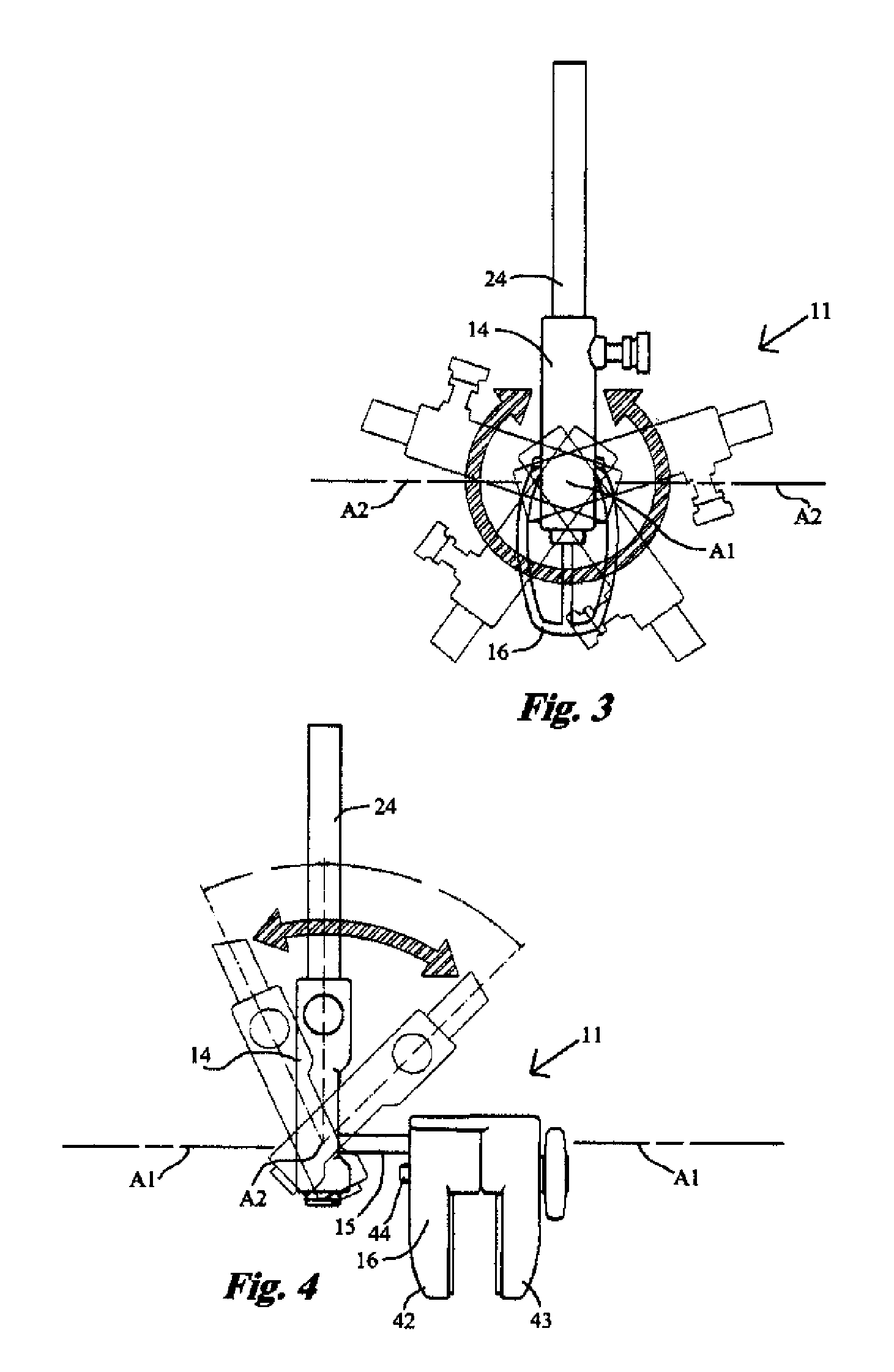
[0019]Referring now to FIGS. 1-6, a pole mounting device 11 embodying features of the present invention includes a holder portion 14, a support portion 15 and a clamp 16. The holder portion 14 is generally tubular and hollow, and is shown as substantially cylindrical. By way of example, and not as a limitation, pole mounting device 11 is shown in FIG. 1 holding a flag pole 24 with a flag 25.

[0020]Describing the specific embodiments herein chosen for illustrating the invention, certain terminology is used which will be recognized as being employed for convenience and having no limiting significance. For example, the terms “front”, “back”, “up”, and “down” will refer to the illustrated embodiment in its normal position of use. The terms “inward” and “outward” will refer to the direction relative to the center of the element being described. Further, all of the terminology above-defined includes derivatives of the word specifically mentioned and words of similar import.

[0021]The holder...


PUM


Abstract

A pole mounting device has a rod with a ball at one end and a clamp at the opposite end, and a holder tube with a ball socket that forms a ball joint with the ball on the end of the rod. The holder tube rotates relative to the rod about two transverse axes. A pole is held in one end of the tube and a set screw in the other end adjusts rotational resistance of the ball joint. The mounting device can mount flag poles, and with an adapter, mobile electronic devices or other articles.

Description

TECHNICAL FIELD[0001]The present invention relates to mounting devices for poles, and more particularly to a pole mounting device that allows rotation of a pole around two axes with adjustable resistance.BACKGROUND ART[0002]Regulations in many states require the raising of a warning flag when a water skier is down in the water in the vicinity of the tow vessel. Often a spotter manually holds the flag. Holding the flag can limit the ability of the spotter to aid the skier or do other tasks.[0003]Some prior known flag holders are rigid, holding the flag pole in a single position, and mount substantially permanently on a tow vessel. The flag must be removed and stowed when the skier skis or is back in the boat, and the flag must be found and inserted when the skier is in the water, with this type of flag holder.[0004]Other prior known flag holders rotate about a single axis. Generally these flag holders must be mounted on a vertical surface, limiting the possible mounting locations. Po...

Claims


Application Information

Patent Timeline
Patent Type & Authority Patents(United States)
IPC IPC(8): F16M13/00
CPCA63B55/008E04H12/2269G09F17/00A63B55/08A63B2055/082A63B2220/12A63B2220/13A63B2225/685A63B2243/0029B63B17/00B63B2017/0054B63B2201/00G09F2017/0083A63B55/408A63B55/60A63B2055/602A63B2102/32
Inventor BUCHNER, MICHAEL R.
Owner BUCHNER MICHAEL R
Why Eureka
Try Eureka