Absorbent pad having zones with different flexibilities

a flexible, absorbent pad technology, applied in the field of absorbent pads, can solve the problems of unreliable that the pad could be kept in close contact with the wearer's body, sideways leakage of bodily fluid, and pad bent, and achieve the effect of sufficient spatial allowance and easy deformation

Inactive Publication Date: 2009-06-16
UNI CHARM CORP
View PDF14 Cites 82 Cited by
  • Summary
  • Abstract
  • Description
  • Claims
  • Application Information

AI Technical Summary

Benefits of technology

[0008]In view of the problems as have been described above, it is an object of this invention to provide an absorbent pad affording an excellent fit particularly in a region of the pad destined to come in contact with a wearer's crotch region.

Problems solved by technology

However, it is unreliable that the pad could be kept in close contact with the pad wearer's body so far as the region of the pad other than the depressed region is concerned.
In other words, there is an anxiety that so-called sideways leakage of bodily fluid might occur in the region of the pad being not in close contact with the wearer's body.
However, there is a possibility that the pad might be bent in the opposite direction to create a U-shape under a body weight of the wearer.

Method used


Image

  • Absorbent pad having zones with different flexibilities
  • Absorbent pad having zones with different flexibilities
  • Absorbent pad having zones with different flexibilities

Examples


first embodiment

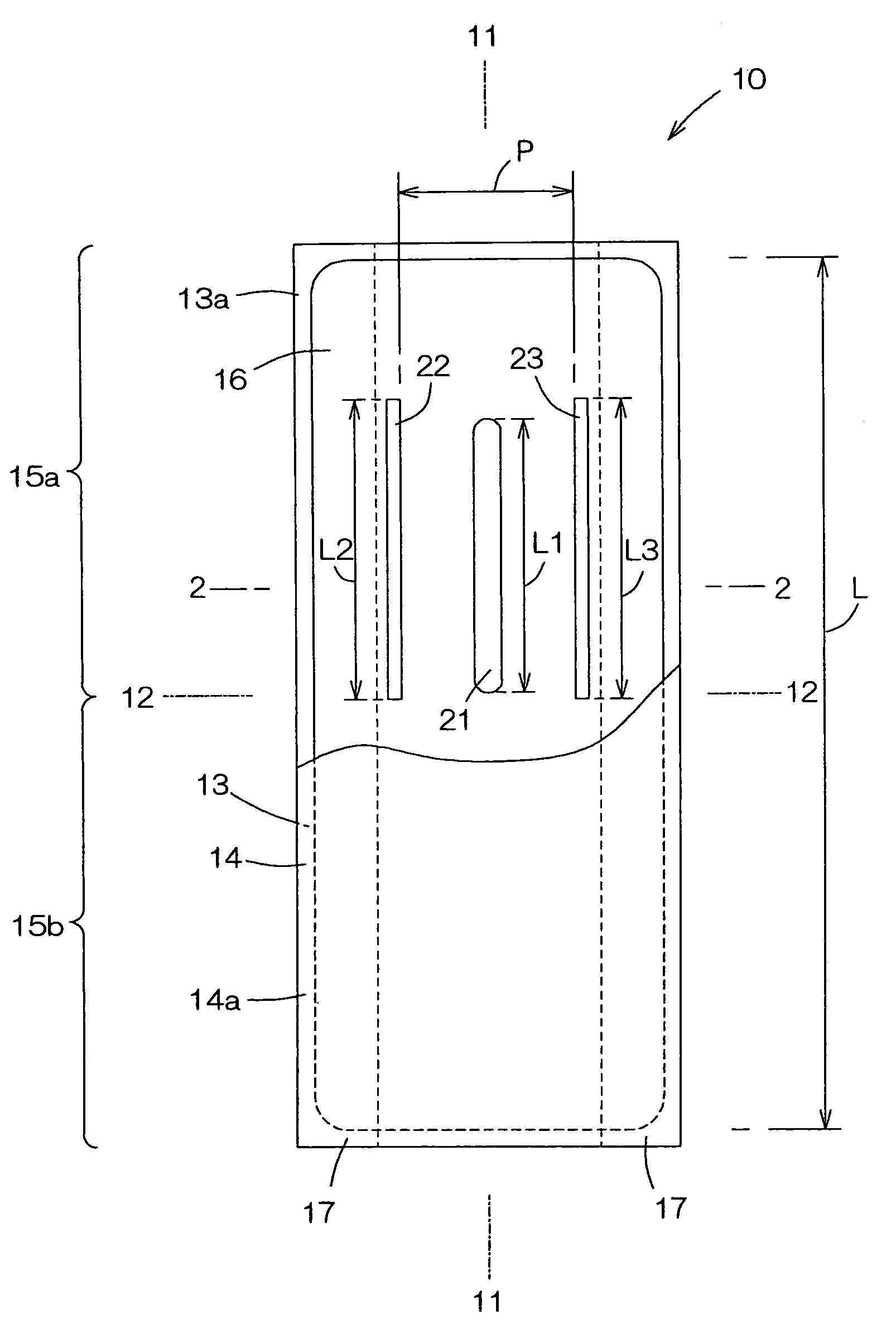
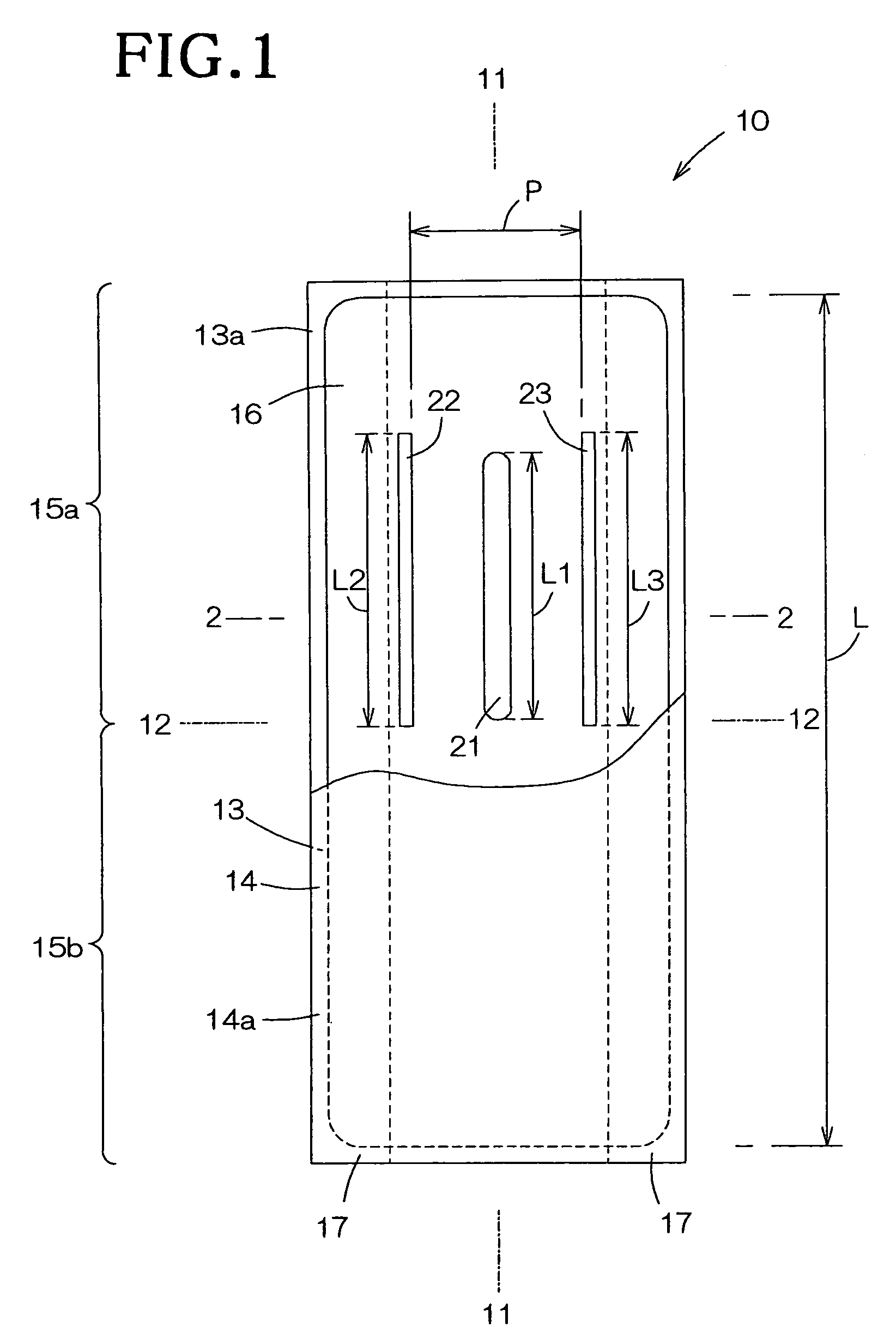
[0041]FIG. 1 is a partially cutaway plan view showing a first embodiment of the absorbent pad according to this invention as viewed from its rear side, FIG. 2 is a sectional view taken along the line 2-2 in FIG. 1 and FIG. 3 is a sectional view taken along the same line as in FIG. 2, showing the first embodiment as put on the wearer's body.

[0042]As will be seen in FIG. 1, the absorbent pad includes an absorbent fibrous structure 10. The absorbent fibrous structure 10 has a longitudinal axis 11, a transverse axis 12 which is orthogonal to the longitudinal axis 11, a front surface destined to come in contact with the wearer's body, a lower surface 14 opposite to the top surface, and front and rear regions 15a, 15b which line up in a direction along the longitudinal axis 11. The absorbent fibrous structure 10 primarily comprises a liquid-permeable topsheet 13a defining the upper surface 13, a hydrophobic backsheet 14a defining the lower surface 14 and a liquid-absorbent core 16 interpo...

second embodiment

[0060]FIG. 4 is a sectional view similar to FIG. 2, showing a second embodiment of the absorbent pad according to this invention. Primary components / members as well as primary regions in the absorbent pad according to this second embodiment corresponding to those in the first embodiment are denoted by the same reference numerals as those in the first embodiment but added with 100, respectively, and details of them will not be repetitively described.

[0061]The absorbent pad according to the second embodiment is distinguished from the absorbent pad according to the first embodiment in that a pair of grooves 122, 123 is depressed not only from a lower surface 114 but also from an upper surface 113. The paired grooves 122, 123 are depressed from the upper surface 113 by depth dimensions H2a, H3a of preferably about 1.00 to 2.50 mm, respectively, and the paired grooves 122, 123 are depressed from the lower surface 114 by a depth dimensions H2b, H3b of preferably about 2 to 4 mm, respectiv...

third embodiment

[0063]FIG. 5 is a partially cutaway plan view similar to FIG. 1, showing a third embodiment of the absorbent pad according to this invention.

[0064]Primary components / members as well as primary regions in the absorbent pad according to this third embodiment corresponding to those in the first embodiment are denoted by the same reference numerals as those in the first embodiment but added with 200, respectively, and details of them will not be repetitively described.

[0065]The absorbent pad according to this third embodiment is distinguished from the absorbent pad according to the first embodiment in that a pair of grooves 222, 223 intermittently extends in the direction defined by a longitudinal axis 211 and describes circular arcs which are convex toward a linear through-hole 221. In this case, the shortest distance between the paired grooves 222, 223 is preferably about 60 to 80 mm.

[0066]The feature that these paired grooves 222, 223 describe circular arcs each convex toward the lin...


PUM


Abstract

A disposable absorbent pad includes an absorbent fibrous structure having a longitudinal axis, a transverse axis, and front and rear regions aligned with each other in a direction along the longitudinal axis. The pad has a flexibility of the front region higher than in rear region.

Description

RELATED APPLICATIONS[0001]The present application is based on, and claims priority from, Japanese Application Serial Number 2004-286344, filed Sep. 30, 2004, the disclosure of which is hereby incorporated by reference herein in its entirety.BACKGROUND OF THE INVENTION[0002]This invention relates to an absorbent pad and more particularly to a disposable absorbent pad providing a good fit to a pad wearer's body.[0003]Various absorbent pads of such a type have conventionally been well known, for example, a disposable absorbent pad provided on the side facing the wearer's garment with a depressed region extending in a longitudinal direction of the pad (REFERENCE 1); a disposable absorbent pad provided in a vicinity of transversely opposite side edges with a pair of regions depressed from the upper surface toward the lower surface of the pad (REFERENCE 2); or a disposable absorbent pad provided on both the side facing the wearer's body and the side facing away from the wearer's body with...

Claims


Application Information

Patent Timeline
Patent Type & Authority Patents(United States)
IPC IPC(8): A61F13/15A61F13/20
CPCA61F13/4704A61F13/4752A61F13/4756A61F13/476A61F13/533A61F13/536
Inventor OHASHI, NAOTOOKU, TOMOMIKAWAKAMI, HIKARIKAMIYAMA, RYUICHI
Owner UNI CHARM CORP
Why Eureka
Try Eureka