Red emitting luminescent materials

a luminescent material and red-emitting technology, applied in the field of new luminescent materials, can solve the problems that trace amounts of additives may also be present in bulk compositions, and achieve the effect of increasing the luminescence and optical properties of at least one ceramic material

Active Publication Date: 2012-04-10
LUMILEDS
View PDF16 Cites 26 Cited by
  • Summary
  • Abstract
  • Description
  • Claims
  • Application Information

AI Technical Summary

Benefits of technology

[0005]It is an object of the present invention to provide a material which is usable within a wide range of applications and especially allows the fabrication of phosphor warm white pcLEDs with optimized luminous efficiency and color rendering.
[0013]Such a material has shown for a wide range of applications within the present invention to have at least one of the following advantages:
[0014]Using the material as luminescent material, LEDs may be built which show improved lighting features, especially thermal stability.
[0031]Without being bound to any theory, the inventors believe that with an increase of x a so called “flux effect” is also increased, which lowers the reaction temperatures needed to manufacture the inventive material.
[0032]However, an increase of x is also believed to widen the half-width of the emission band. This may be advantageous for some application within the present invention, especially if the material is doped with Ce(III) because a broad emission band in the green to amber spectral region is especially useful for a luminescent material used as color converter in white phosphor converted LEDs.
[0042]According to a preferred embodiment, the at least one ceramic material has a density of ≧90% and ≦100% of the theoretical density. This has been shown to be advantageous for a wide range of applications within the present invention since then the luminescence and optical properties of the at least one ceramic material may be increased.

Problems solved by technology

However, in some applications, trace amounts of additives may also be present in the bulk compositions.

Method used


Image

  • Red emitting luminescent materials
  • Red emitting luminescent materials
  • Red emitting luminescent materials

Examples


example ii

[0079]FIGS. 5 and 6 refer to SrAlSi4N7: Eu(3%) which was made analogous to SrAlSi4N7: Eu(2%) (cf. Example I)

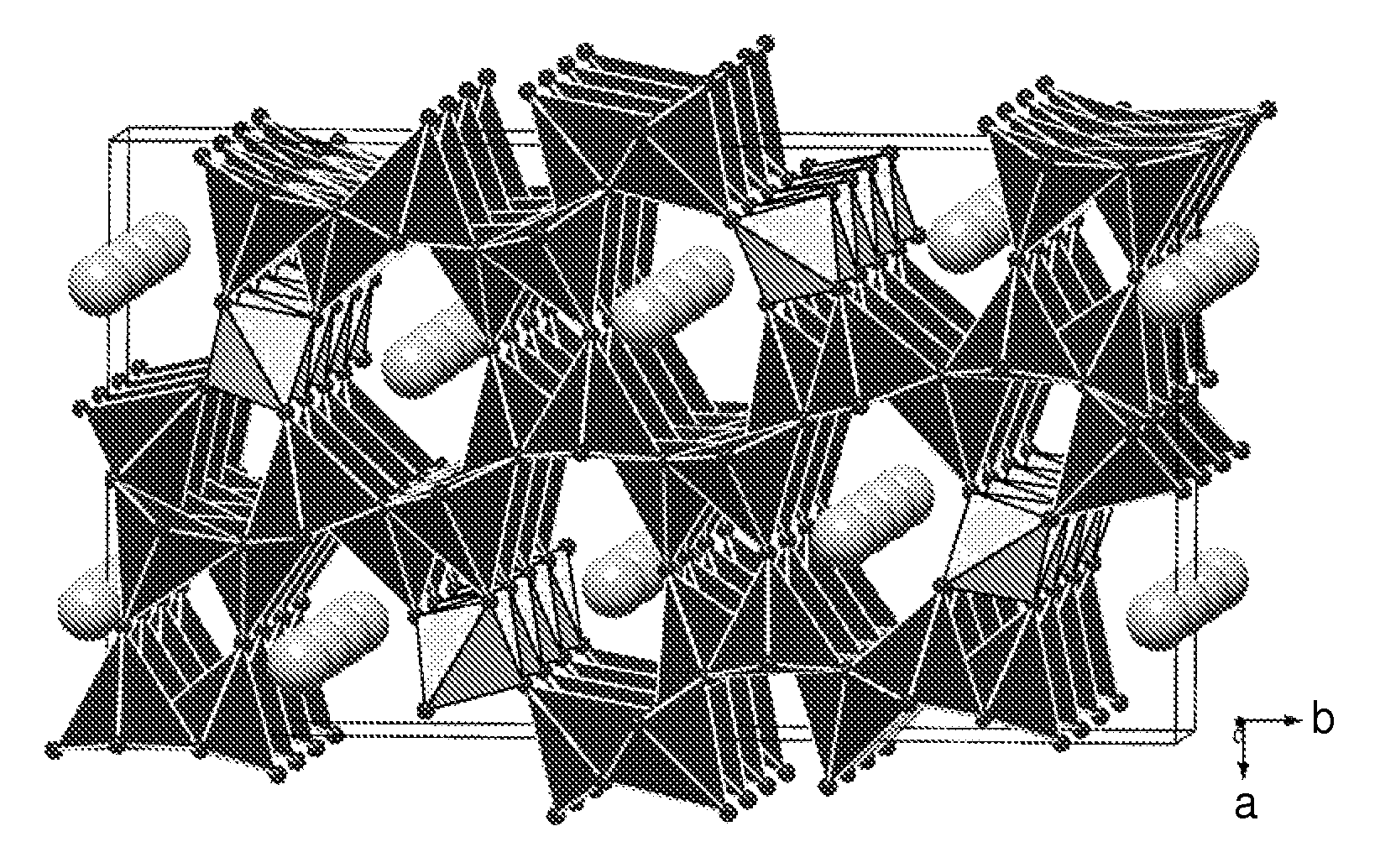
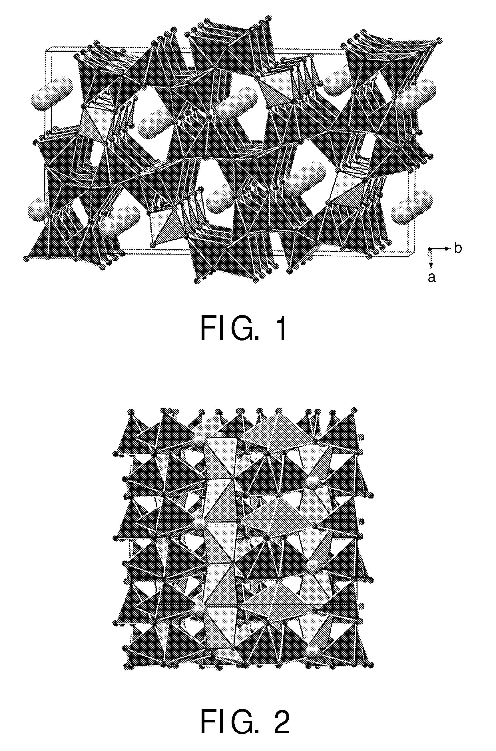
[0080]FIG. 1 shows a schematic perspective partial view of the host material of the structure of Example I, i.e. SrAlSi4N7, FIG. 2 shows the same structure from another perspective. It can be clearly seen, how the SiN4 and AlN4 tetraeders form lattices.

[0081]The exact crystal data can be seen in Table I:

[0082]

TABLE 1Crystal data of SrAlSi4N7.chemical formulaSrAlSi4N7molar mass / g · mol−1325.03crystal systemorthorhombicspace groupPna21 (No. 33)lattice parameters / pma = 1174.2(2), b = 2139.1(4), c = 496.6(1)cell volume / 106 pm31247.2(4)formula units in unit cell4

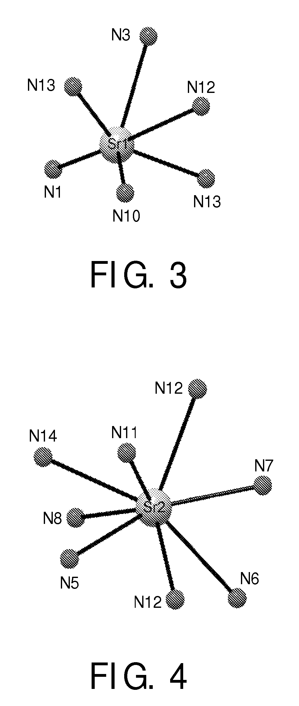
[0083]FIG. 3 and FIG. 4 show the M(1) and M(2)-sites in the material of example I, i.e. SrAlSi4N7: Eu(2%). It can be clearly seen that the two sites are different which has the believed effects as described above.

[0084]The exact data for the host material (i.e. the undoped SrAlSi4N7) is given in Table II:

[0085]

TABLE IIatomi...


PUM

PropertyMeasurementUnit
temperatureaaaaaaaaaa
diameteraaaaaaaaaa
surface roughnessaaaaaaaaaa

Abstract

The invention relates to an improved red light emitting material of the formula M1−yA1+xSi4−xN7−x−2yOx+2y:RE whereby M is selected out of the group comprising Ba, Sr, Ca, Mg or mixtures thereof, A is selected out of the group comprising Al, Ga, B or mixtures thereof, RE is selected out of the group comprising rare earth metals, Y, La, Sc or mixtures thereof and x is ≧0 and ≦1 and y is ≧0 and ≦0.2. This material is believed to crystallize in a novel structure type that comprises two individual lattice sites for rare 10 earth metal incorporation, which leads to an improved lighting behavior.

Description

FIELD OF THE INVENTION[0001]The present invention is directed to novel luminescent materials for light emitting devices, especially to the field of novel luminescent materials for LEDs and their use in light emitting devices. The invention also relates to a light emitting device comprising such material and a system comprising light emitting devices.BACKGROUND OF THE INVENTION[0002]Phosphors comprising silicates, phosphates (for example, apatite) and aluminates as host materials, with transition metals or rare earth metals added as activating materials to the host materials, are widely known. As blue LEDs, in particular, have become practical in recent years, the development of white light sources utilizing such blue LEDs in combination with such phosphor materials is being energetically pursued.[0003]Especially red emitting luminescent materials have been in the focus of interest and several materials have been proposed, e.g. U.S. Pat. No. 6,680,569(B2), “Red Deficiency Compensatin...

Claims


Application Information

Patent Timeline
Patent Type & Authority Patents(United States)
IPC IPC(8): C09K11/02H01J29/10
CPCC09K11/7706H01L33/502C04B35/584C04B35/597C09K11/7734C04B2235/6565C04B2235/6567C04B2235/77C04B2235/963C04B2235/3213C04B2235/3217C04B2235/3865C04B2235/3873C04B2235/40C04B2235/401C04B2235/5409C04B2235/5436C04B2235/5445C04B2235/5454C04B2235/6562C09K11/7774C09K11/77348C09K11/77H05B33/14
Inventor SCHMIDT, PETER J.MAYR, WALTERMEYER, JOERGSCHNICK, WOLFGANGHECHT, CORA SIEGLINDESTADLER, FLORIAN
Owner LUMILEDS
Why Eureka
Try Eureka