White emitting light source and luminescent material with improved colour stability

a technology of luminescent materials and white light sources, which is applied in the direction of luminescent compositions, light and heating apparatuses, electric circuit arrangements, etc., can solve the problems of poor color rendering in the red spectral region and the cumbersome fabrication of white leds, and achieve the effect of optimizing luminous efficiency and color rendering

Active Publication Date: 2013-06-18
LUMILEDS
View PDF13 Cites 3 Cited by
  • Summary
  • Abstract
  • Description
  • Claims
  • Application Information

AI Technical Summary

Benefits of technology

[0004]It is an object of the present invention to provide an illumination system which is usable within a wide range of applications and especially allows the fabrication of warm white pcLEDs with optimized luminous efficiency and color rendering.
[0007]Such an illumination system has shown for a wide range of applications within the present invention to have at least one of the following advantages:
[0008]The colour control of the illumination system can be greatly enhanced due to the fact that for a wide range of applications within the present invention changes in the blue wavelength of the excitation source are compensated by spectral shift in the conversion layer.
[0010]The invented luminescent material shows excellent thermal and photo-thermal stability of the luminescence efficiency, this in combination with the above leads to a highly temperature stable illumination system.
[0025]According to a preferred embodiment of the present invention, the ratio [M]:[Si], i.e. (b+y):(c+x), in said at least one luminescent material is ≧1.01 and ≦1.20. By doing so it has been surprisingly found that the (photo-) thermal stability may for a wide range of applications within the present invention be increased even further.
[0040]According to a preferred embodiment, the at least one ceramic material has a density of ≧90% and ≦100% of the theoretical density. This has been shown to be advantageous for a wide range of applications within the present invention since then the luminescent properties of the at least one ceramic material may be increased.

Problems solved by technology

White LEDs based on a single YAG:Ce luminescent colour converter usually reach Ra values in the 70s with very bad colour rendering in the red spectral region.
However fabrication of white LEDs becomes more cumbersome due to the added degrees of freedom.

Method used


Image

  • White emitting light source and luminescent material with improved colour stability
  • White emitting light source and luminescent material with improved colour stability
  • White emitting light source and luminescent material with improved colour stability

Examples


example i

[0075]Example I refers to

1.080(CaN2 / 3)*1.006(AlN)*0.963(SiN4 / 3)*0.0198CeO3 / 2*0.0002EuO*0.018SiO2*0.014AlO3 / 2

which was prepared in the following fashion:

[0076]All actions were carried out in dry inert gas atmosphere. 53.37 g Ca3N2 (2N), 41.02 g AlN (3N), 0.78 g Al2O3, 45.30 g Si3N4, 1.09 g SiO2, 3.41 g CeO2 (4N) and 0.035 g Eu2O3 (4N) were intimately mixed by ball milling and the mixture was subsequently fired in forming gas atmosphere (N2:H2 95:5 v / v) at 1500° C. maximum temperature. The obtained powder cake was again milled, granulated and pressed into pellets by uniaxial pressing and subsequent cold isostatic pressing until a green density of >50% was reached. The pellets were sintered at 1650° C. in forming gas atmosphere, optionally this is followed by a hot isostatic pressing step at 1 kbar N2 to improve the density.

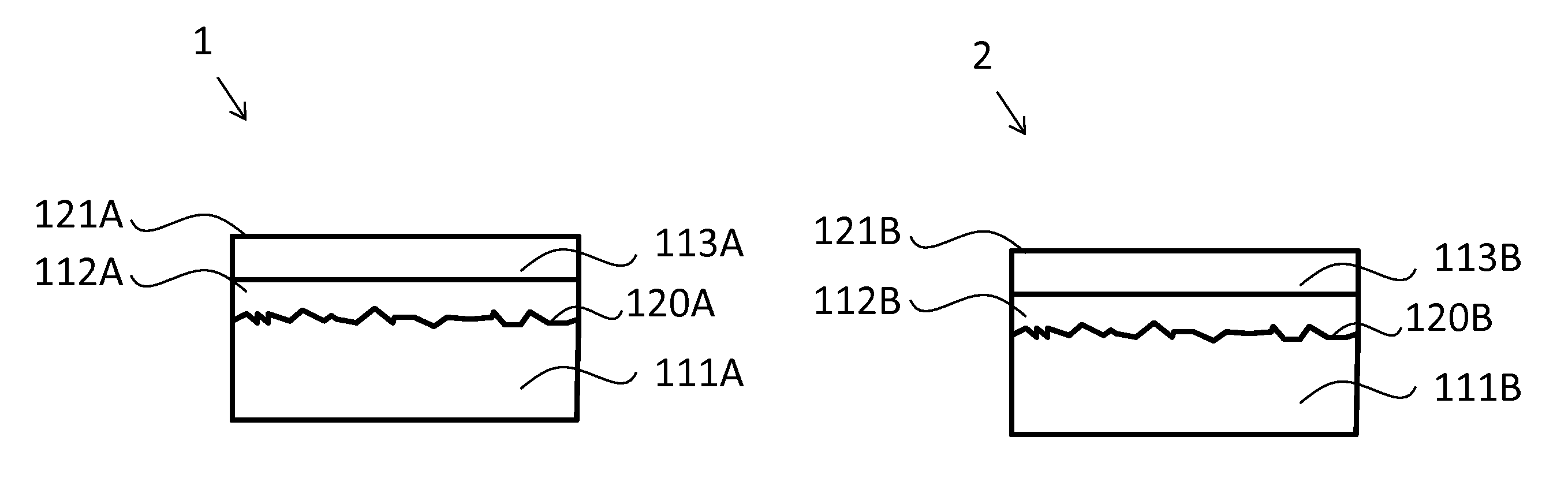
[0077]FIG. 7 shows a blue LED 1 and a blue LED 2 (=illuminations systems). Each of n-GaN layers 111A, 111B of LEDs 1, 2 are optically coupled by transparent glue 1...


PUM

PropertyMeasurementUnit
FWHMaaaaaaaaaa
FWHMaaaaaaaaaa
FWHMaaaaaaaaaa

Abstract

The invention relates to a white emitting light source with an improved luminescent material of the formula (AEN2 / 3)*b (MN)*c (SiN4 / 3)*d1 CeO3 / 2*d2 EuO*x SiO2*y AlO3 / 2 wherein AE is an alkaline earth metal chosen of the group of Ca, Mg, Sr and Ba or mixtures thereof and M is a trivalent element chosen of the group of Al, B, Ga, Sc with d1>10*d2. In combination with a UV to blue light generating device this material leads to an improved light quality and stability, especially an improved temperature stability for a wide range of applications.

Description

FIELD OF THE INVENTION[0001]The present invention is directed to novel luminescent materials for light emitting devices, especially to the field of novel luminescent materials for LEDs.BACKGROUND OF THE INVENTION[0002]For illumination purposes high CRI light sources are generally preferred. White LEDs based on a single YAG:Ce luminescent colour converter usually reach Ra values in the 70s with very bad colour rendering in the red spectral region. Therefore strong pressures exist for the development of efficient illumination grade white LEDs with excellent colour rendering over the entire visible spectral region. The obvious measure to improve colour rendering is the addition of a red emitting luminescent material (i.e. disclosed in the U.S. Pat. No. 6,717,353). However fabrication of white LEDs becomes more cumbersome due to the added degrees of freedom. Thus single phosphor options are deemed to be favourable if not superior.[0003]However, there is still the continuing need for nov...

Claims


Application Information

Patent Timeline
Patent Type & Authority Patents(United States)
IPC IPC(8): F21V9/16
CPCC01B21/0602H01L33/502C04B35/581C04B35/583C04B35/584C04B35/6455C09K11/0883C09K11/7792C09K11/7734C01P2004/61C04B2235/3217C04B2235/3224C04B2235/3229C04B2235/3418C04B2235/3852C04B2235/386C04B2235/3865C04B2235/3873C04B2235/604C04B2235/608C04B2235/6582C04B2235/9646H01L2924/0002C01P2002/84H01L2924/00C09K11/77928
Inventor MEYER, JOERGBECHTEL, HANS-HELMUTMAYR, WALTERSCHMIDT, PETERSCHREINEMACHER, BABY-SERIYATIWIECHERT, DETLEF UWE
Owner LUMILEDS
Why Eureka
Try Eureka