Prover self testing and validation apparatus

a prover and self-testing technology, applied in the direction of liquid/fluent solid measurement, volume/mass flow by differential pressure, instruments, etc., can solve the problem of generating an error signal to achieve the effect of detecting fluid flow

Active Publication Date: 2012-04-24
FLOW MANAGEMENT DEVICES
View PDF26 Cites 18 Cited by
  • Summary
  • Abstract
  • Description
  • Claims
  • Application Information

AI Technical Summary

Problems solved by technology

If there is not equivalence between the volume and rate of flow of the fluid with preset parameters, an error signal to that effect will be generated.

Method used


Image

  • Prover self testing and validation apparatus
  • Prover self testing and validation apparatus
  • Prover self testing and validation apparatus

Examples


Embodiment Construction

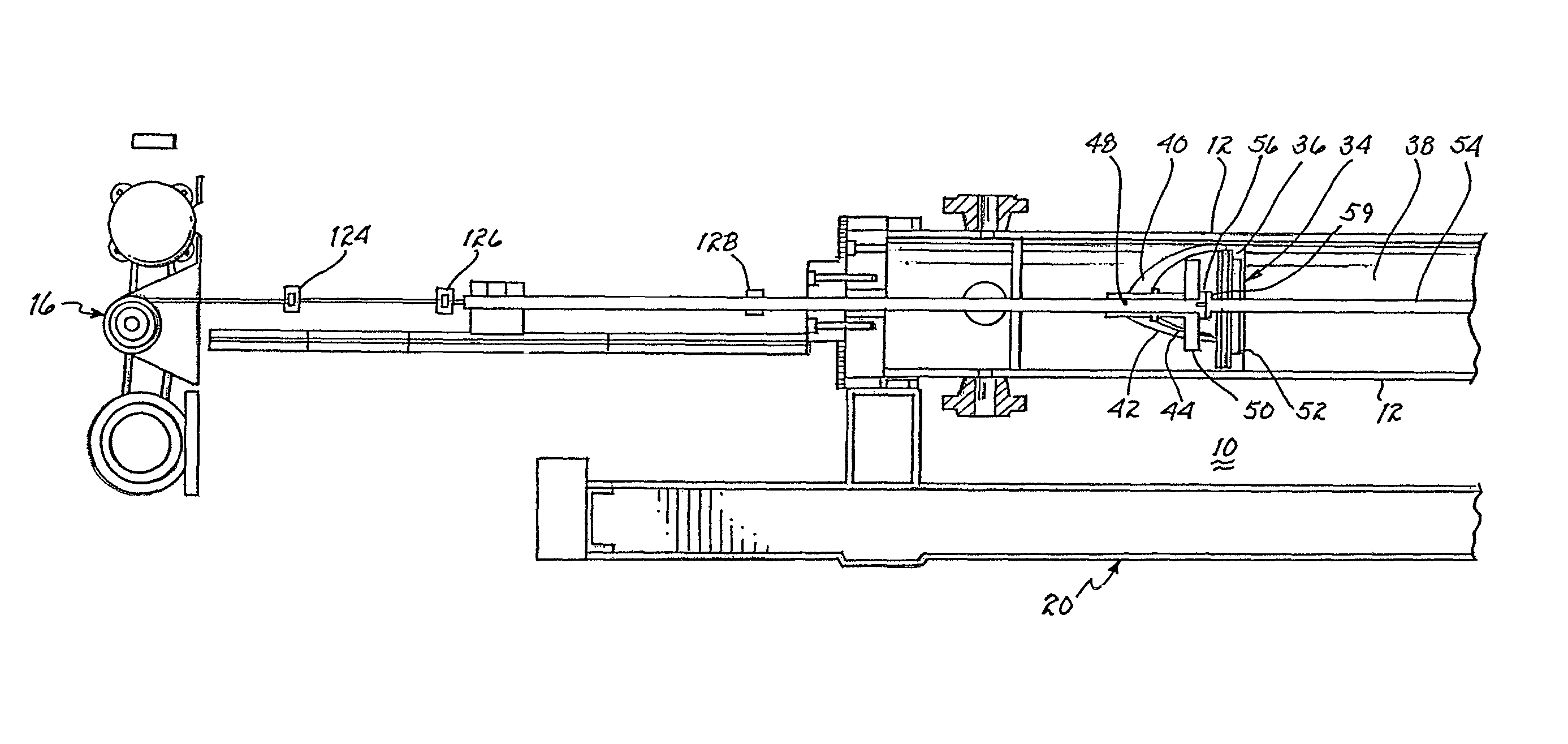
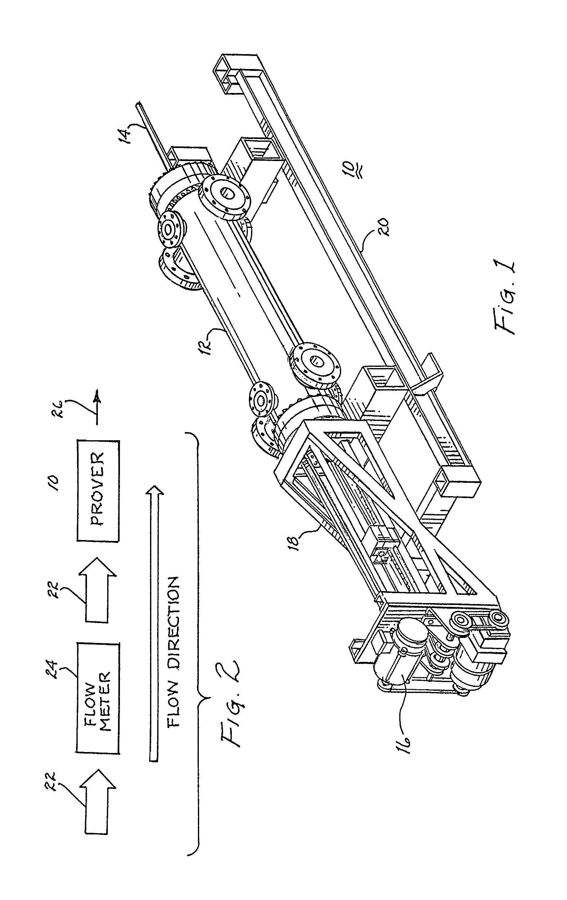
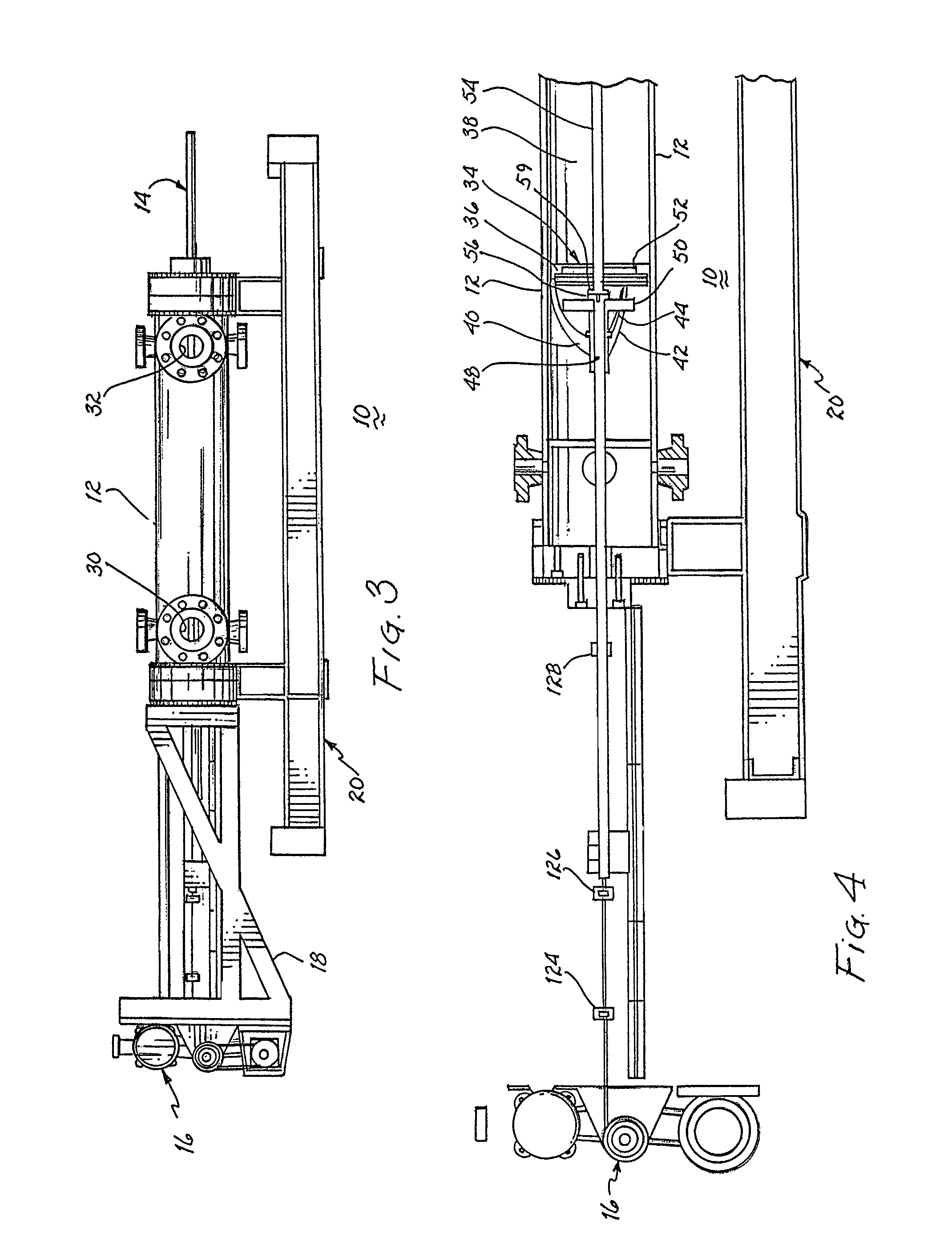
[0028]Referring to FIG. 1, there is illustrated a unidirectional captive displacement prover 10. The prover includes a cylinder 12 having a rectilinearly translatable piston with a poppet valve disposed therein and mounted on a rod 14. Motive means, generally identified by reference numeral 16, is supported upon a frame 18 attached to and extending from cylinder 12. The motive means imparts a force to rod 14 to cause translation in one direction of the piston within the cylinder. A clutch accommodates free translation of the rod and piston in the other direction.

[0029]Prover 10 is mounted upon a framework 20 that is attached at a location generally adjacent a flow meter 24 (see FIG. 2) to be periodically tested. As particularly shown in FIG. 2, a fluid 22 flows through a flow meter 24, which flow meter is to be tested, and into prover 10. Outflow from the prover is channeled into a conduit for the fluid, as represented by arrow 26. The prover includes various sensors and test equipm...


PUM


Abstract

A prover includes a piston supporting rod extending longitudinally through a cylinder, which cylinder receives and discharges a fluid to measure the volume and flow rate of the fluid by translation of the piston from the fluid receiving end to the fluid discharging end. Motive means includes at least one element for drawing the rod and piston toward the fluid receiving end of the cylinder. Travel of the piston in the direction from the fluid receiving end to the fluid discharging end of the cylinder is sensed at discrete locations to provide an indication of the quantity of fluid therebetween and the related flow rate. Each of a plurality of switches, linear encoder or laser detector provides position sensing signals reflective of the volume and rate of fluid flowing in the cylinder. These signals, representative of this volume and flow rate, are compared with preset parameters to determine the degree of equivalence. Thereby, self testing and validation occurs.

Description

CROSS REFERENCE TO RELATED APPLICATIONS[0001]The present application is a continuation-in-part application of an application entitled “METHOD FOR MOUNTING A PROVER”, filed Jan. 6, 2010 and assigned Ser. No. 12 / 652,820, which is a divisional application of an application entitled “UNIDIRECTIONAL CAPTIVE DISPLACEMENT PROVER” filed Jan. 10, 2008, and assigned Ser. No. 11 / 972,530, now U.S. Pat. No. 7,650,775.FIELD OF THE INVENTION[0002]The invention relates to the field of measuring fluid flow and, more particularly, to self testing and validating apparatus for a prover.BACKGROUND OF THE INVENTION[0003]In order to obtain accurate readings from a flow meter or prover, it must be calibrated periodically by determining its characteristic or K-factor. The K-factor is a constant of proportionality between the flow rate of the fluid flowing through the flow meter and the response provided by the flow meter to the flow rate. A typical turbine type flow meter develops electrical oscillations pr...

Claims


Application Information

Patent Timeline
Patent Type & Authority Patents(United States)
IPC IPC(8): G01P21/00
CPCG01F25/0015G01F25/11
Inventor IGNATIAN, ALEXANDER
Owner FLOW MANAGEMENT DEVICES
Why Eureka
Try Eureka