
Roofing membrane retainer

a technology for roof decking and retainers, which is applied in the direction of fastening devices, washing machines, mechanical devices, etc., can solve the problems of increasing the likelihood of roofing membrane puncture or tear, limited width and difficult installation of roof decking membranes

Active Publication Date: 2012-05-01
TALAN PRODS
View PDF51 Cites 62 Cited by
  • Summary
  • Abstract
  • Description
  • Claims
  • Application Information

AI Technical Summary

Benefits of technology

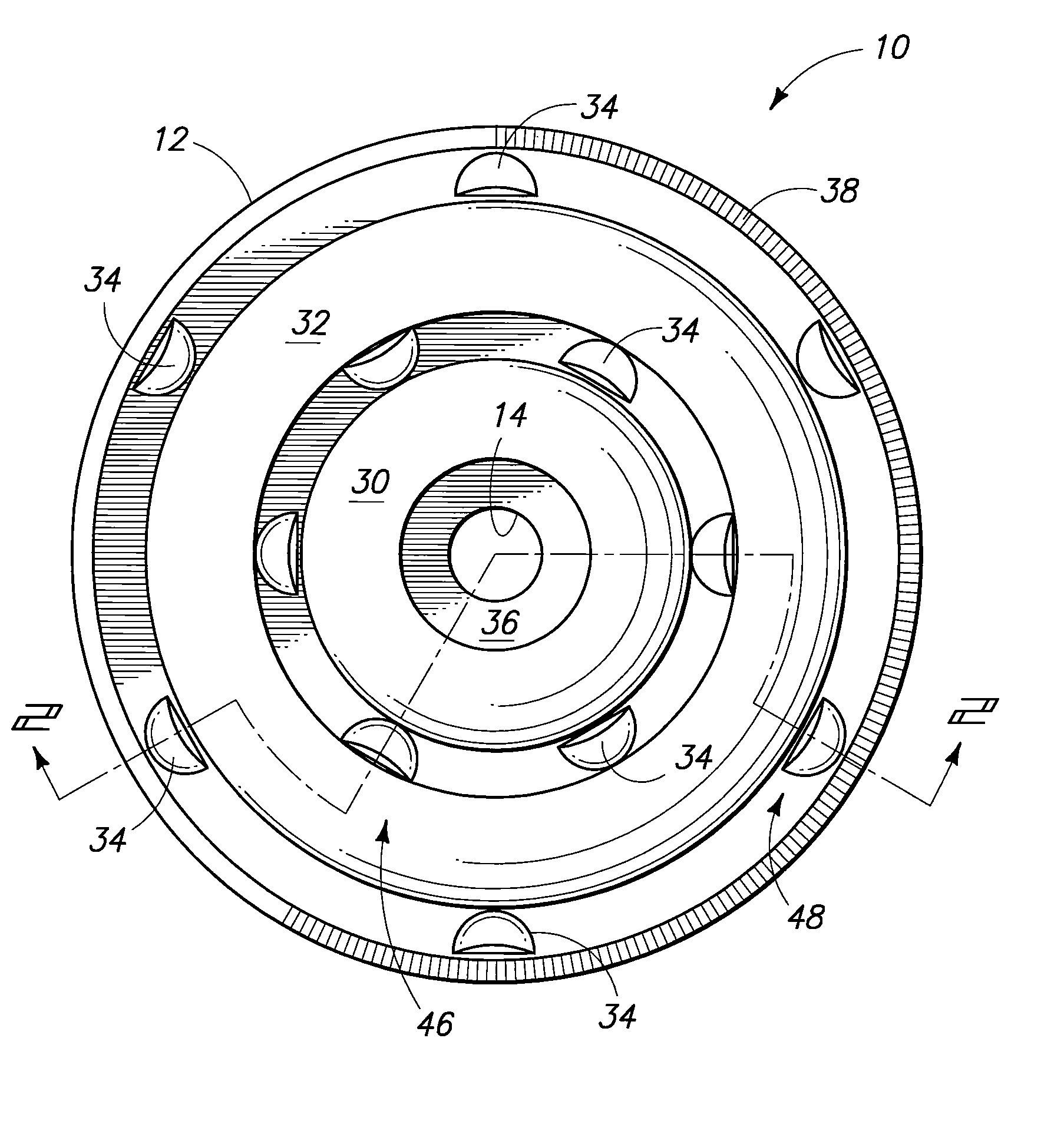
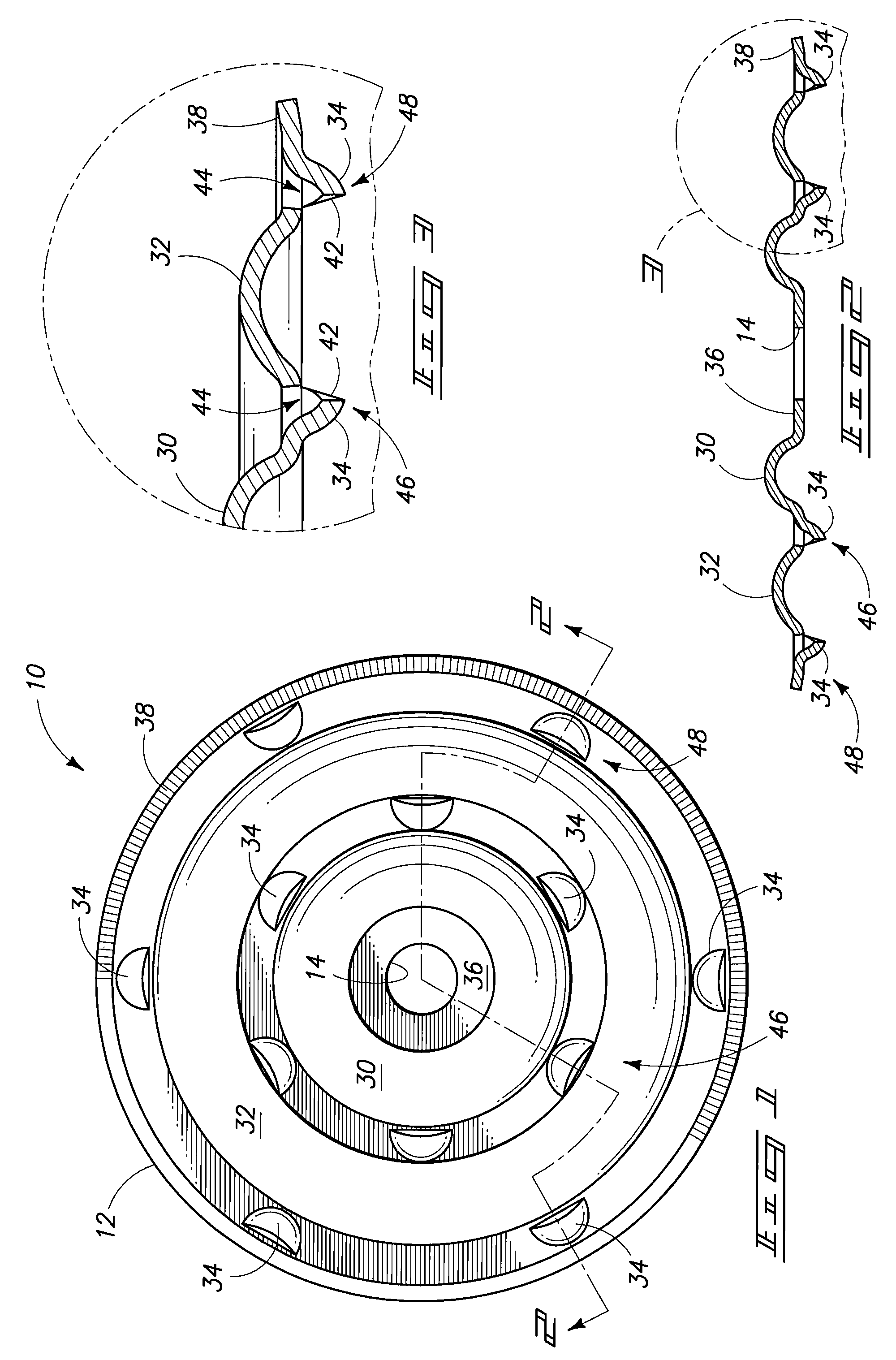
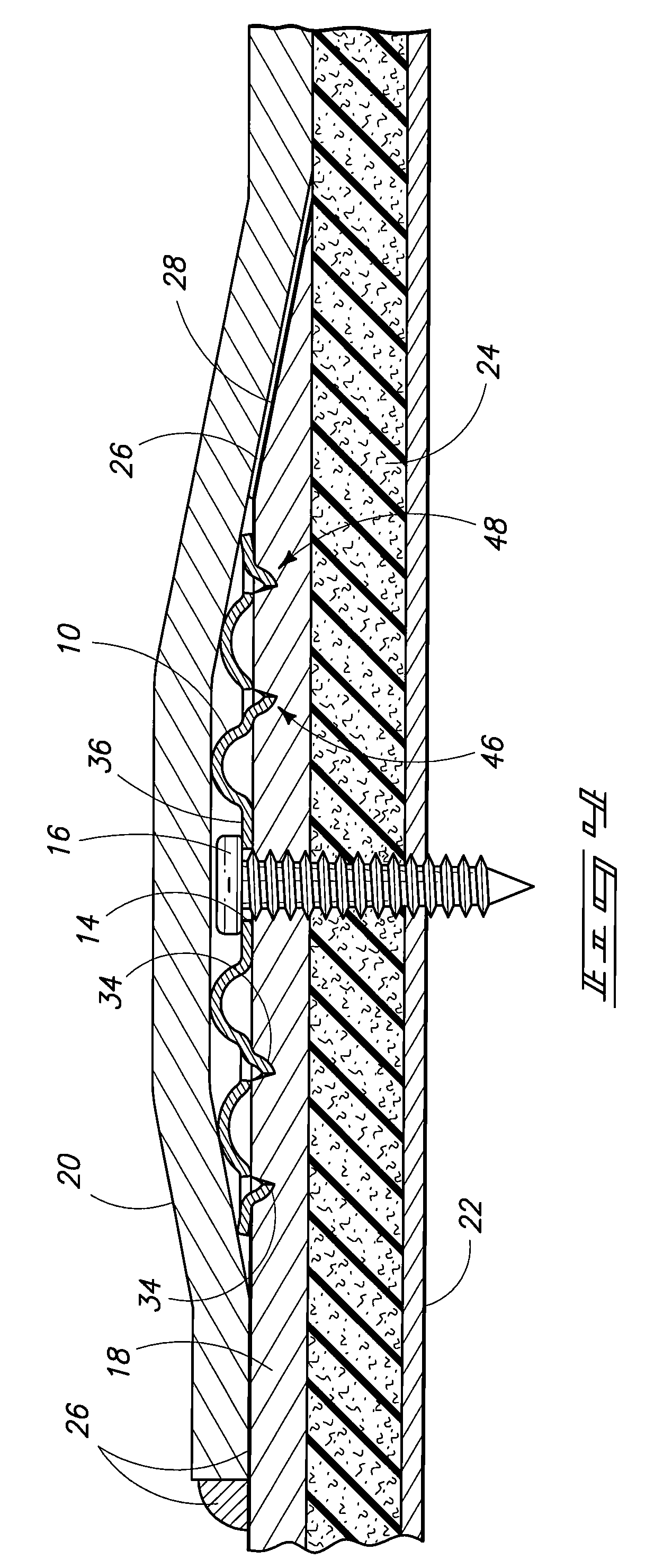
"The patent text describes a roofing membrane retainer that has projections that grip roofing membranes without puncturing them. The retainer has a cylindrical plate with inner and outer raised reinforcing ribs and scoop-shaped projections that extend downward from the plate in concentric inner and outer arrays. The projections have an open mouth edge and a remaining peripheral portion contiguous with the plate. The mouth edge of adjacent projections is oriented in alternating radial inward and outward directions. The retainer can be used to securely hold the membrane in place during construction or repair without causing any damage."

Problems solved by technology

More particularly, roof decking membranes are of limited width relative to a roof structure, necessitating placement of membranes adjacent or in overlapping arrangement.
However, the presence of sharp prongs on a seam plate tends to increase the likelihood that the roofing membrane will puncture or tear when subjected to wind loads or other in-use loads.
Secondly, the prongs on such seam plates make installation more difficult as roofing installers retrieve by hand individual seam plates from within a container, or bucket and the prongs tend to cut and abrade their fingers and hands.
Such points tend to increase the likelihood that a membrane will be torn under severe loading conditions which can lead to failure of the fastening system and tearing of the membrane.
Secondly, the two corners on each v-shaped projection can also lead to undesirable cutting and abrading of the hands of a roofing installer.

Method used


Image

  • Roofing membrane retainer
  • Roofing membrane retainer
  • Roofing membrane retainer

Examples


Embodiment Construction

[0020]This disclosure of the invention is submitted in furtherance of the constitutional purposes of the U.S. Patent Laws “to promote the progress of science and useful arts” (Article 1, Section 8).

[0021]Reference will now be made to preferred embodiments of Applicant's invention comprising a roofing membrane retainer. While the invention is described by way of preferred embodiments, it is understood that the description is not intended to limit the invention to such embodiments, but is intended to cover alternatives, equivalents, and modifications which may be broader than the embodiments, but which are included within the scope of the appended claims.

[0022]In an effort to prevent obscuring the invention at hand, only details germane to implementing the invention will be described in great detail, with presently understood peripheral details being incorporated by reference, as needed, as being presently understood in the art.

[0023]FIG. 1 illustrates a retainer plate 10 for use in a...


PUM


Abstract

A roofing membrane retainer is provided having a cylindrical plate. The cylindrical plate has a central aperture for receiving a fastener. The plate also includes a pair of concentric inner and outer raised reinforcing ribs and a plurality of scoop-shaped projections. The scoop-shaped projections extend downwardly from the plate in concentric inner and outer cylindrical arrays. The inner cylindrical array of projections and the outer cylindrical array of projections are radially outward of the inner rib and the outer rib, respectively. The projections each comprise a scoop with a base periphery having an open mouth edge and a remaining peripheral portion contiguous with the plate. The projections in each array are spaced equidistance about the plate. The mouth edge of adjacent projections are oriented in alternating radial inward and outward directions.

Description

TECHNICAL FIELD[0001]This invention pertains to retention and connection systems for roof decking membranes. More particularly, the present invention relates to roofing membrane retainers and seam plates.BACKGROUND OF THE INVENTION[0002]It is well known to use roofing membrane retainers, or seam plates in order to retain roof decking membranes atop roof decking substructures. More particularly, roof decking membranes are of limited width relative to a roof structure, necessitating placement of membranes adjacent or in overlapping arrangement. These constructions are well-known in the art. U.S. Pat. No. 4,945,699 to Murphy illustrates one roofing seam plate suitable for retaining membranes atop a roof decking substructure. Typically, an insulation layer is placed atop a steel roof decking structure, after which membranes are rolled thereatop. A seam plate is applied along the membrane edge with a screw fastener, driving the screw through the insulation panel and into the decking to r...

Claims


Application Information

Patent Timeline
Patent Type & Authority Patents(United States)
IPC IPC(8): E04B5/00
CPCE04D5/142E04D5/145F16B43/00
Inventor GARRIGUS, PETER C.PARZIALE, PAT
Owner TALAN PRODS
Learn More