
Inflatable shutter

a shutter and inflatable technology, applied in the field of shutters, can solve the problems of damage to the window glazing, labor-intensive removal of such conventional shutter systems, damage to the appearance of the building exterior,

Inactive Publication Date: 2012-05-08
QMI SECURITY SOLUTIONS
View PDF35 Cites 16 Cited by
  • Summary
  • Abstract
  • Description
  • Claims
  • Application Information

AI Technical Summary

Benefits of technology

"The present invention is an inflatable shutter that can be used to cover an opening in a building structure. It consists of a protective layer and at least one air bladder positioned between the protective layer and the building structure, creating a protective cavity. The inflatable shutter can be mounted over the opening using a fastener. The technical effect of this invention is that it provides a flexible and effective solution for protecting openings in building structures, reducing the risk of damage or unauthorized access."

Problems solved by technology

The installation and removal of such conventional shutter systems is often labor intensive and may itself damage or mar the appearance of the building exterior.
Dade county continues to maintain these requirements, even though from an engineering stand-point they make little sense.
In a HVHZ district, the most difficult test to meet is that the protective shutter cannot deflect debris into the opening that could cause damage to the window glazing.
Unfortunately, these same products fail to qualify in areas governed by HVHZ regulations because of how they deflect debris.
However, rigid framed shutters significantly increase the overall system's prices, as well as creating additional engineering problems.
Conventional shutters are heavy and cumbersome due to the size and weight of the materials utilized in their manufacture.
Conventional shutters may weigh 50 lbs or more, making them difficult to handle during installation and removal, particularly when only one person is available for installation or removal.
Furthermore, conventional shutters are bulky and require significant storage space when not in use.

Method used


Image

  • Inflatable shutter
  • Inflatable shutter
  • Inflatable shutter

Examples


Embodiment Construction

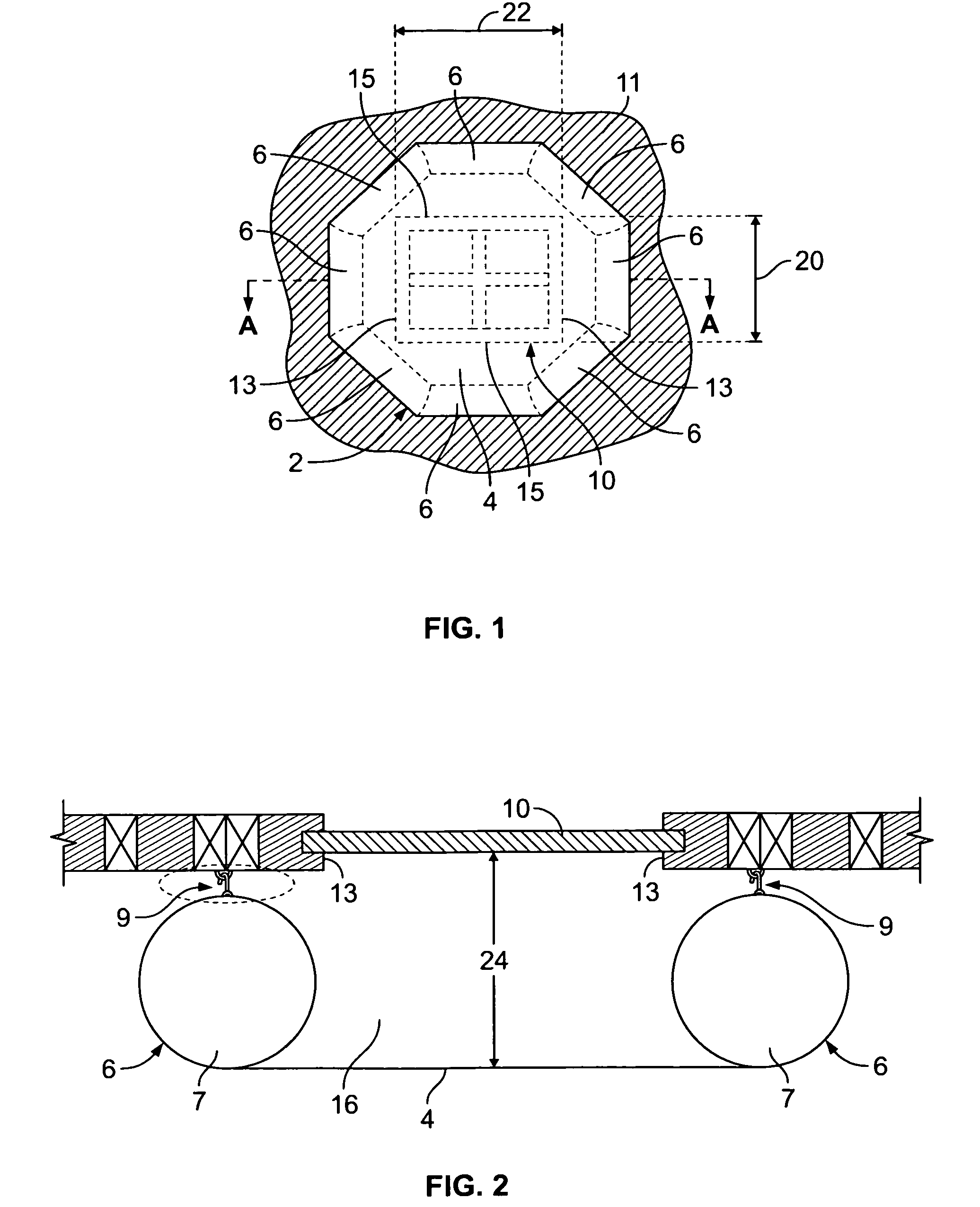
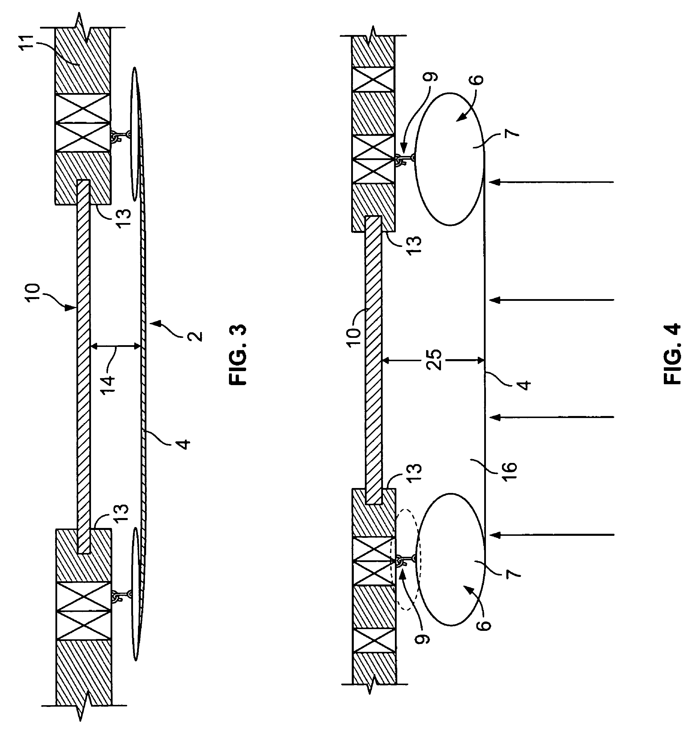
[0022]Referring to FIGS. 1-4, an inflatable shutter is shown installed by a fastener over the opening of a building structure. In the embodiment shown in FIG. 1, the inflatable shutter 2 is secured over a window 10 of a building structure 11. Inflatable shutter 2 comprises a protective layer 4, stretched over a plurality of air bladders 6. Air bladders 6 abut building structure 11 on the longitudinal 13 and / or horizontal 15 edges of the structure, thereby providing a protective cavity 16 (shown in FIG. 2) between protective layer 4 and window 10.

[0023]Referring to FIG. 1, protective layer 4 of inflatable shutter 2 directly receives strong winds and windborne debris. Therefore, it must be dimensioned such that it covers the perimeter of window 10, defined by a height 20 and length 22. As a result, no part of window 10 is exposed. Although inflatable shutter 2 covers a window 10, those of ordinary skill in the art will understand that such a shutter may also be useful over other openi...


PUM

PropertyMeasurementUnit
perimeteraaaaaaaaaa
impact resistance propertiesaaaaaaaaaa
pressureaaaaaaaaaa

Abstract

An inflatable shutter is provided. The shutter comprises a protective layer and at least one air bladder, and is attached to the outside of a building structure. The shutter is positioned outside the building structure adjacent a window or other opening in order to protect the window or other opening from high velocity winds and flying debris during storms. The shutter may be removed from the outside of the building and compactly stored during periods of nonuse.

Description

FIELD OF THE INVENTION[0001]The present invention relates to shutters for use in buildings and, in particular, to inflatable shutters for protection of windows, doors and other exterior openings in a building.[0002]Temporary shutters are commonly used to protect windows, doors, skylights, vents and other exterior openings in buildings from storm damage caused by high velocity winds and impacts from windborne debris. Conventional shutter systems include plywood panels and corrugated panels of steel, aluminum and plastic. The installation and removal of such conventional shutter systems is often labor intensive and may itself damage or mar the appearance of the building exterior. Plywood panels are typically nailed or screwed directly to the building structure. Installation of corrugated panels often involves the attachment of a rigid frame or other hardware to the building structure. In some cases, reinforcement bars may be required to hold the shutters in place.[0003]Requirements fo...

Claims


Application Information

Patent Timeline
Patent Type & Authority Patents(United States)
IPC IPC(8): E04G11/04
CPCE06B9/02E06B7/2318
Inventor MILLER, JAMES V.
Owner QMI SECURITY SOLUTIONS
Learn More