Swivel hook tie down

a technology of hooks and hooks, applied in the direction of snap fasteners, buckles, couplings, etc., can solve the problems of reducing the speed by which cargo may be fastened and unfastened

Active Publication Date: 2012-05-08
TURN 14 DISTRIBUTION INC
View PDF35 Cites 20 Cited by
  • Summary
  • Abstract
  • Description
  • Claims
  • Application Information

AI Technical Summary

Problems solved by technology

As the strap twists, it begins to kink which diminishes the speed by which cargo may be fastened and unfastened.

Method used


Image

  • Swivel hook tie down
  • Swivel hook tie down
  • Swivel hook tie down

Examples


Embodiment Construction

[0014]In the description which follows like parts are marked throughout the specification and drawing with the same reference numerals, respectively. The drawing figures may not necessarily be to scale and certain features may be shown in generalized or somewhat schematic form in the interest of clarity and conciseness.

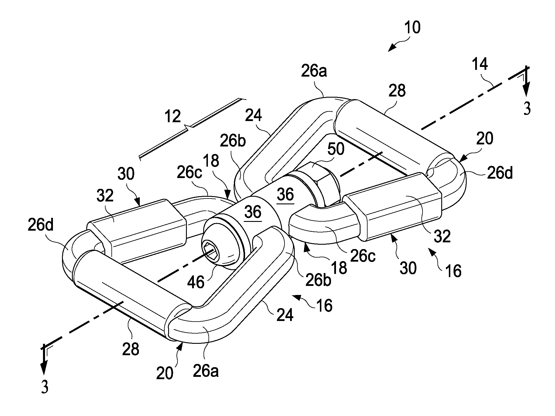
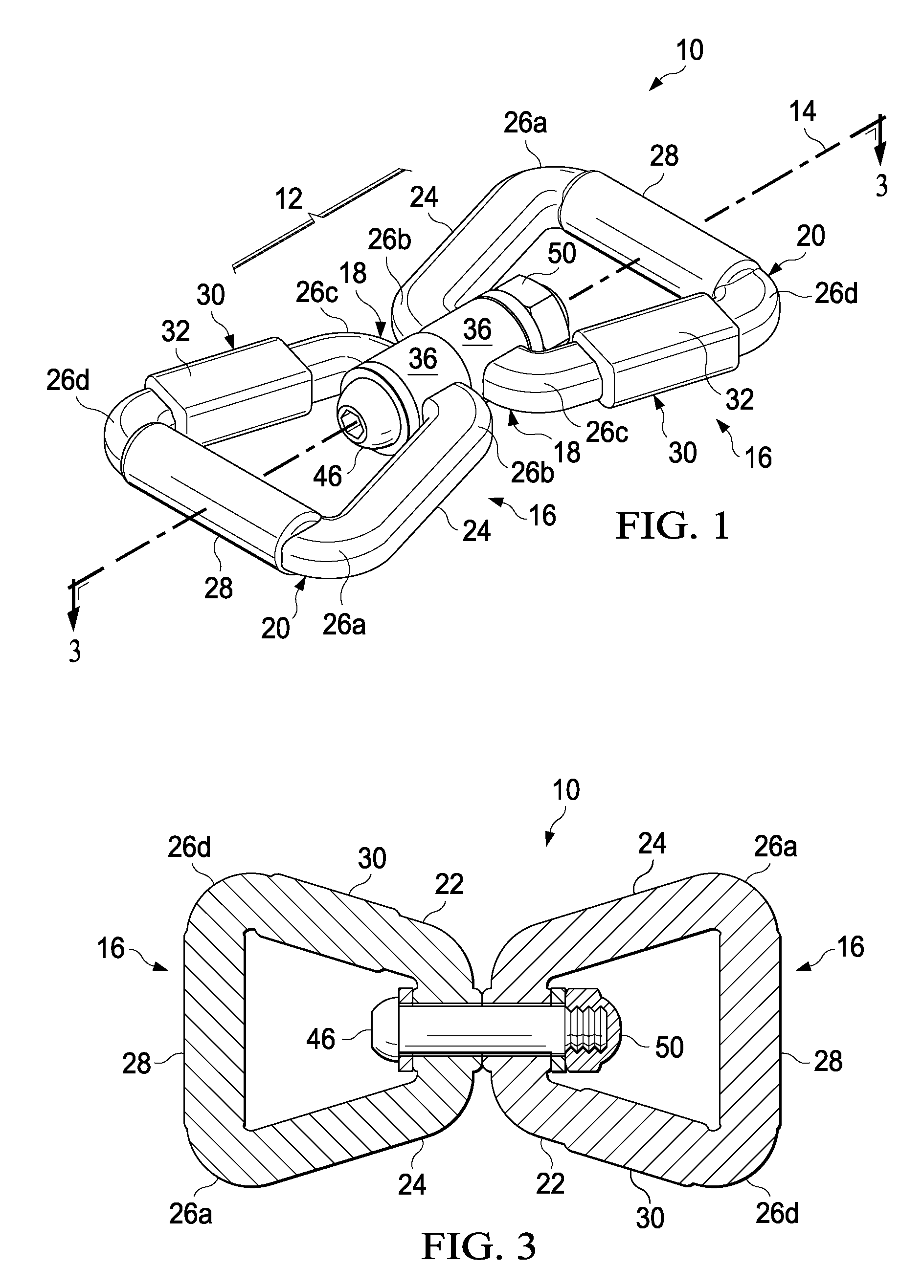
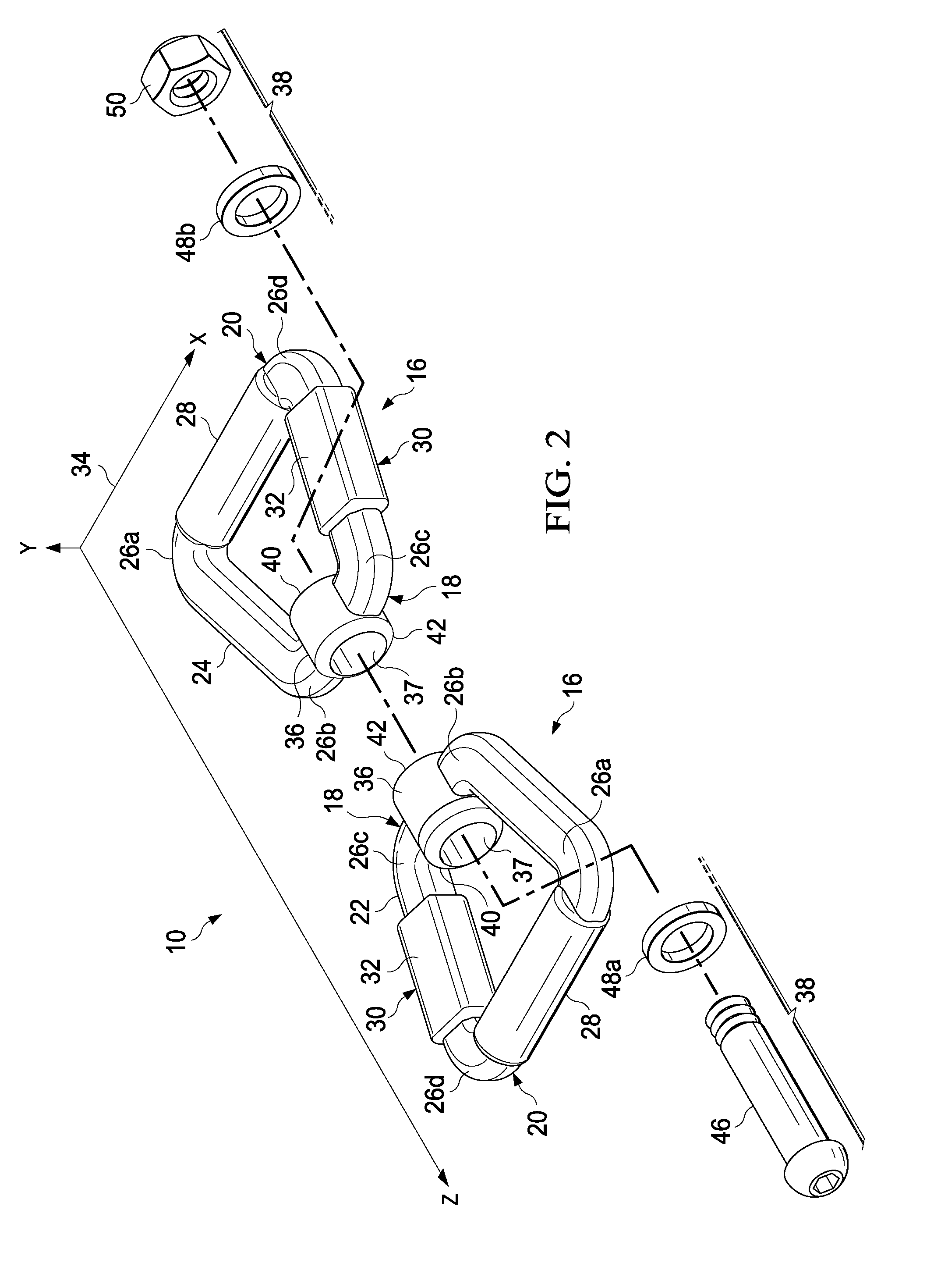
[0015]Referring to FIG. 1, there is illustrated a swivel coupling 10 having two substantially identical “loop” or segment portions 16 connected by a linkage portion 12 that is rotatable about an axis 14 that coincides with the overall axis of the coupling 10. Further describing a loop or segment 16 of the coupling, segment 16 has a substantially trapezoidal configuration or backbone with a short end 18 and a long end 20, with the two ends 18 and 20 connected by first 22 and second side 24 portions, and the ends and sides are connected via shoulder portions 26a-d to form the overall substantially trapezoidal shape having a generally planar configuration as reflected by...


PUM


Abstract

A swivel coupling is provided for connecting a multi-piece restraint having two trapezoidally shaped segments capable of rotating with respect to each other. Each segment includes rectangular and multiple cylindrical portions with one being orthogonal to the segment and having an orifice for receiving a connecting means to join the segments. In another embodiment, one segment is joined to an attachment having a hook that includes a base portion and a hook portion where the base portion includes an orthogonal cylindrical portion having an orifice for receiving a connecting means that extends through the orifice and through the second orifice of the segment.

Description

BACKGROUND OF THE INVENTION[0001]Cargo is often restrained or secured using lengths of materials often referred to as “tie-downs” that are in turn connected to the container, for instance, such as a truck, trailer and the like. Conventional tie-downs are characterized by having a single continuous section of material that may be referred to as a strap with securing means at each end for connection between the cargo and the container. In use, conventional tie-downs twist as cargo moves or as the securing means is tightened, for instance, in the case where strap tension may be adjusted with the securing means attached to the cargo or container. As the strap twists, it begins to kink which diminishes the speed by which cargo may be fastened and unfastened. Accordingly, it is to overcome the disadvantages of conventional tie-downs that the present invention has been developed.SUMMARY OF THE INVENTION[0002]A swivel coupling for connecting a multi-piece restraint is disclosed herein havin...

Claims


Application Information

Patent Timeline
Patent Type & Authority Patents(United States)
IPC IPC(8): F16D3/00
CPCF16B45/00F16G15/08Y10T24/45225Y10T403/32975Y10T24/45288Y10T403/32213F16B45/002
Inventor BERNEY, BRIAN J.
Owner TURN 14 DISTRIBUTION INC
Why Eureka
Try Eureka