Catheter configured for incremental rotation

a catheter and incremental rotation technology, applied in the field of catheters, can solve the problems of difficult or impossible to accurately control the distal rotational orientation of the device, the catheter shaft to exhibit wind-up, and the inability to accurately orient the distal end of the catheter at equally spaced rotational intervals, so as to achieve the effect of increasing the precision of the rotational incremen

Inactive Publication Date: 2012-05-08
ABBOTT CARDIOVASCULAR
View PDF9 Cites 39 Cited by
  • Summary
  • Abstract
  • Description
  • Claims
  • Application Information

AI Technical Summary

Benefits of technology

[0007]This invention is directed to a catheter which allows the rotational orientation of the distal end of the catheter to be adjusted in discrete intervals as the physician rotates the proximal end of the catheter. The catheter is designed to intentionally induce whipping in a controlled manner in which the rotational spacing of the shaft minimum energy storage rotational orientations is set to the desired rotational interval, and / or an operative distal end portion of the catheter is in a desired rotational orientation relative to a shaft minimum energy storage rotational orientation. As a result, the operative distal end of the catheter is easily and accurately oriented in a patient's body lumen during a medical procedure, which can result in a number of benefits such as more accurately and thoroughly treating or diagnosing a region in a shorter amount of time.
[0013]In another embodiment, a catheter of the invention generally comprises an elongated tubular shaft having a proximal end, a distal end, and a tubular member with a section along which a wall of the shaft has two or more strips circumferentially spaced apart by portions of the wall having a different flexural modulus than the strips, and along which the shaft has an average flexural modulus (averaged over a full rotation) substantially equal to an average flexural modulus of longitudinally adjacent portions of the shaft along which the strips do not extend. The different flexural modulus strips (i.e., the flexural modulus along the strips is increased or decreased relative to the portions of the shaft wall circumferentially spaced between the strips) could be formed by the voids of the previous embodiment or by a variety of suitable methods including strips of higher or lower modulus material in or on the shaft. However, despite the presence of the different flexural modulus strips, an average flexural modulus of the shaft does not change relative to immediately adjacent proximal and distal sections of the shaft which don't have the strips. As a result, larger differences in energy storage between the maximum and minimum shaft energy storage rotational orientations may be attained while minimizing kinking, torsion buckling or other failures of the shaft at the incremental rotation inducing section. Larger differences in energy storage between the maximum and minimum shaft energy storage conditions may be desired to make the applied torque changes during catheter rotation more detectable and / or to increase rotational increment precision. Failures of the shaft which would otherwise be made more likely (i.e., caused to occur at lower force levels) by the presence of the incremental rotation inducing section can additionally or alternatively be prevented or minimized (i.e., caused to occur at higher force levels) by limiting the difference between the stored energy of the maximum and minimum stored energy orientations (i.e., the flexural modulus provided by the different flexural strips is not disadvantageously much greater or lesser than the flexural modulus of the shaft wall portions circumferentially therebetween).

Problems solved by technology

However, in the construction of elongated intravascular catheters, one difficultly has been the tendency of the catheter shaft to exhibit wind-up and whipping in the anatomy, which makes it difficult to accurately orient the operative distal end at equally spaced rotational intervals by rotating the proximal end of the catheter.
Because unintentionally induced whipping can make it very difficult or impossible to adequately control the distal rotational orientation of the device by rotating the proximal end, a design objective in many conventional percutanteous catheters, especially where rotational orientation control is desired, is to minimize whipping.
However, a consistent flexural modulus may require features such as consistent wall thickness, consistent / linear elastic material properties, the spiraling of shaft components, and / or concentric shaft designs, which are most often not practical to include or obtain.
However, this results in the catheter being limited to a single easily attained rotational orientation relative to the curved conduit, and is not useful when two or more catheter rotational orientations relative to the curved conduit, or a rotational increment of other than 360 degrees, are desired.

Method used


Image

  • Catheter configured for incremental rotation
  • Catheter configured for incremental rotation
  • Catheter configured for incremental rotation

Examples


Embodiment Construction

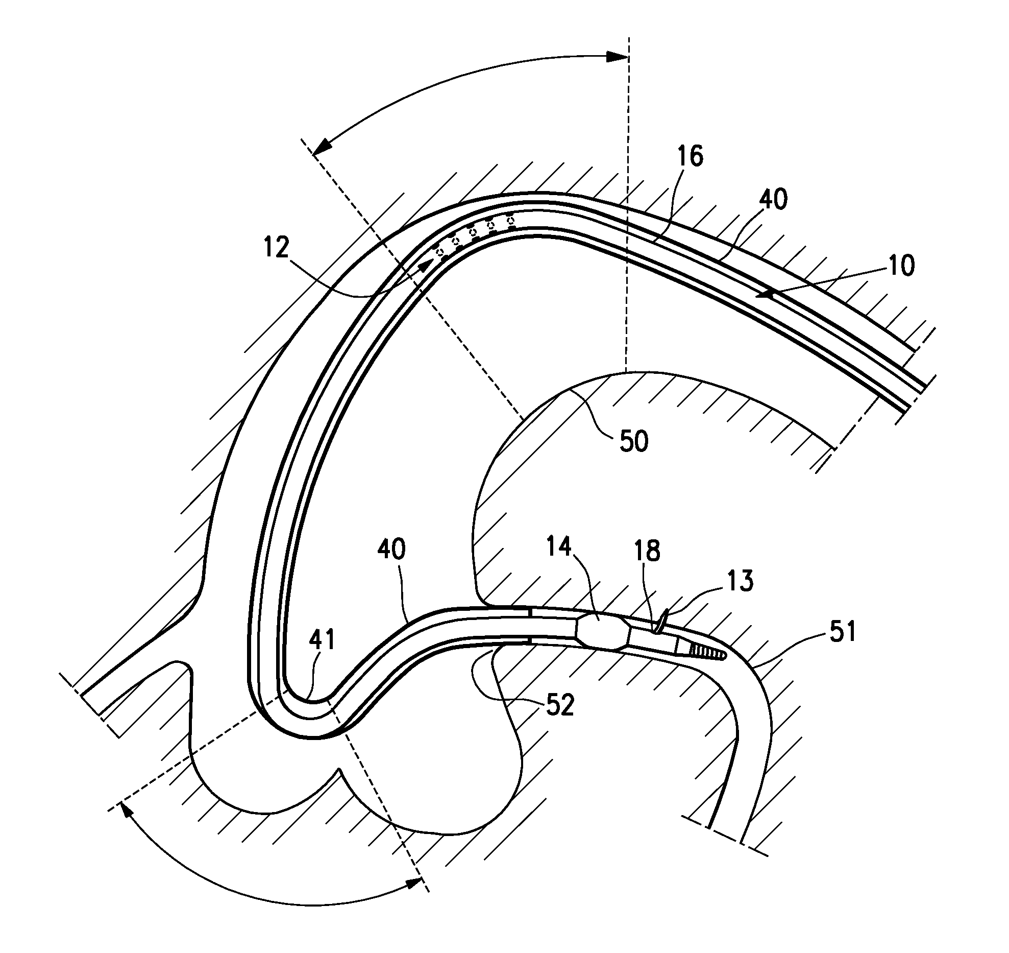
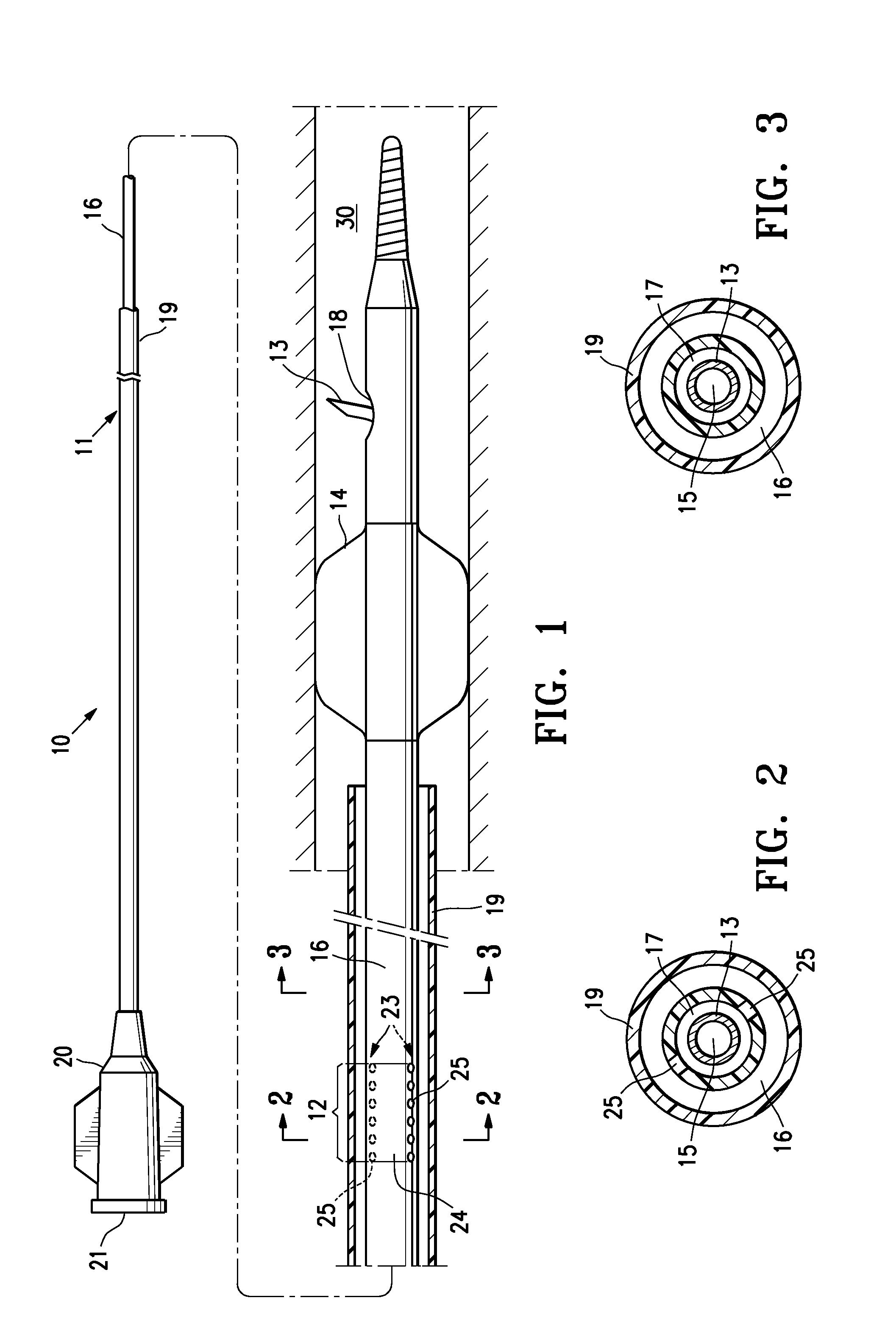
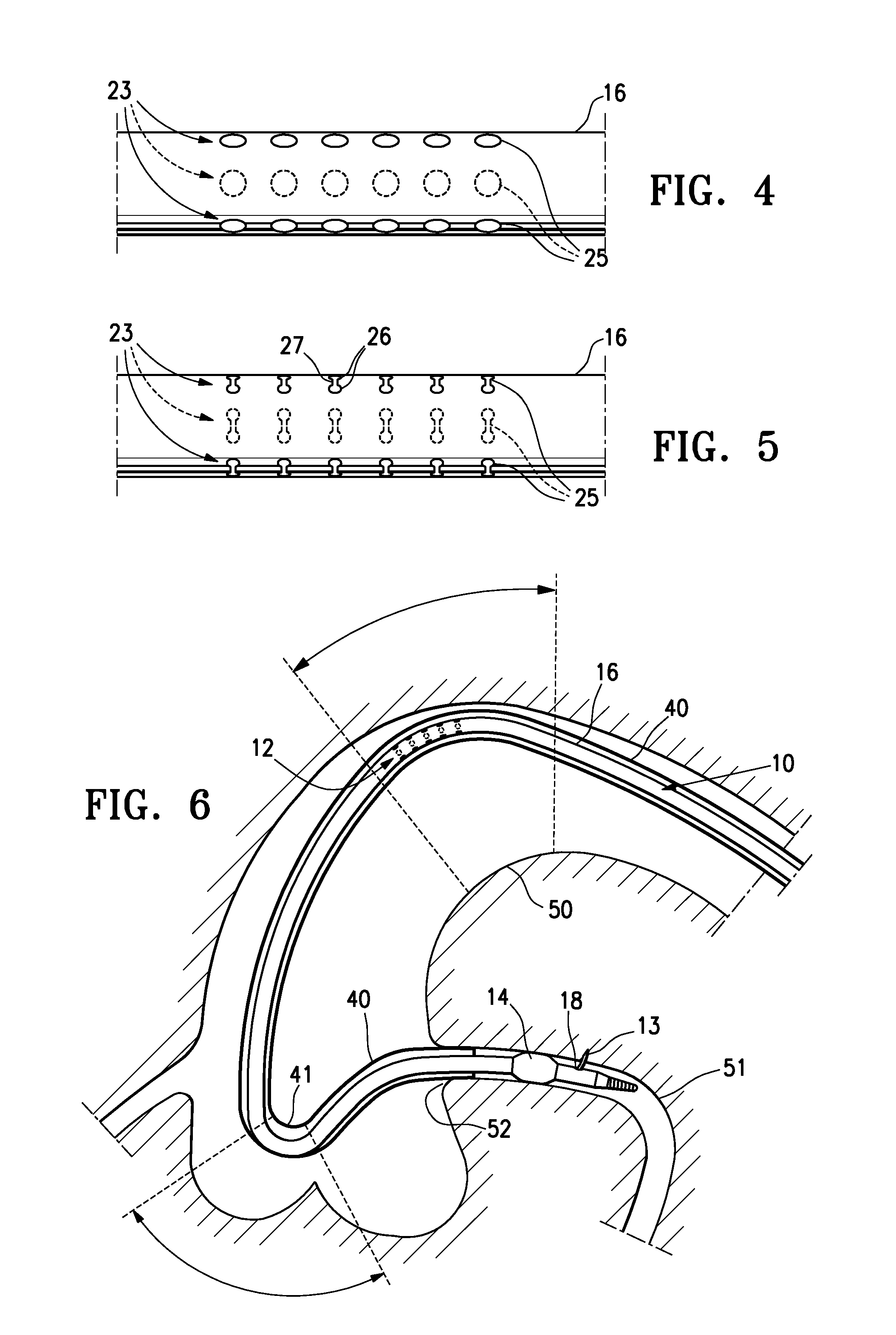
[0021]FIG. 1 is an elevational, partially in section, view of a catheter 10 embodying features of the invention, generally comprising an elongated tubular shaft 11 having a proximal end, a distal end, and incremental rotation inducing features 12 in a wall of the shaft 11. The catheter 10 is a needle catheter having a needle 13 which is slidably disposed in the shaft 11 and which reversibly extends from the shaft in an extended configuration. In the illustrated embodiment, the needle catheter 10 further includes a radially expandable member 14 mounted on a distal shaft section. The radially expandable member 14 is configured to expand against the inner surface of the patient's body lumen 30, to thereby temporarily center and stabilize the location of the catheter in the body lumen 30. A variety of suitable radially expandable members 14 can be used including open-walled cages or inflatable balloons. In an embodiment in which the expandable member 14 is a balloon with an inflatable i...


PUM


Abstract

A catheter which allows the rotational orientation of the distal end of the catheter to be adjusted in discrete intervals as the physician rotates the proximal end of the catheter. The catheter is designed to intentionally induce whipping but to limit the amount of whipping to a desired rotational interval.

Description

BACKGROUND OF THE INVENTION[0001]The invention relates to the field of medical devices, and more particularly to catheters, such as needle catheters or other elongated devices configured for inserting into a patient's body lumen or cavity to perform a diagnostic and / or therapeutic procedure.[0002]During a treatment or diagnostic procedure using an interventional catheter slidably disposed in a patient's coronary or peripheral vasculature, it may be necessary to rotate the catheter to properly position an operative distal end component in a specific rotational orientation relative to the treatment location in the patient's anatomy. For example, in a drug delivery procedure using a needle catheter, the ability to rotate the distal tip of the catheter would facilitate performing injections at multiple adjacent locations to more fully treat an area of the patient's anatomy. Typically, the physician attempts to orient the distal end of the catheter inside the patient by rotating the prox...

Claims


Application Information

Patent Timeline
Patent Type & Authority Patents(United States)
IPC IPC(8): A61M25/00
CPCA61M25/0052A61M25/0054A61M2025/0089A61P9/00A61P9/10
Inventor WEBLER, JR., WILLIAM E.
Owner ABBOTT CARDIOVASCULAR
Why Eureka
Try Eureka