
Differential magnetoresistive magnetic head

a magnetic head and magnetoresistive technology, applied in the field of differential magnetoresistive magnetic heads, can solve the problems of difficult to realize the function of a storage device, inability to achieve high resolution in the linear density direction, and limited geometrical gap of the magnetic shield, so as to achieve high resolution and high manufacturing stability. , the effect of high resolution

Inactive Publication Date: 2012-05-08
WESTERN DIGITAL TECH INC
View PDF13 Cites 16 Cited by
  • Summary
  • Abstract
  • Description
  • Claims
  • Application Information

AI Technical Summary

Benefits of technology

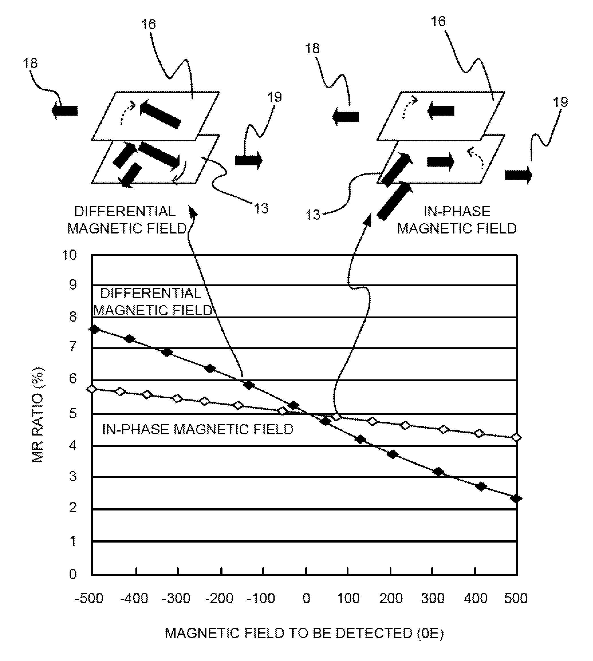
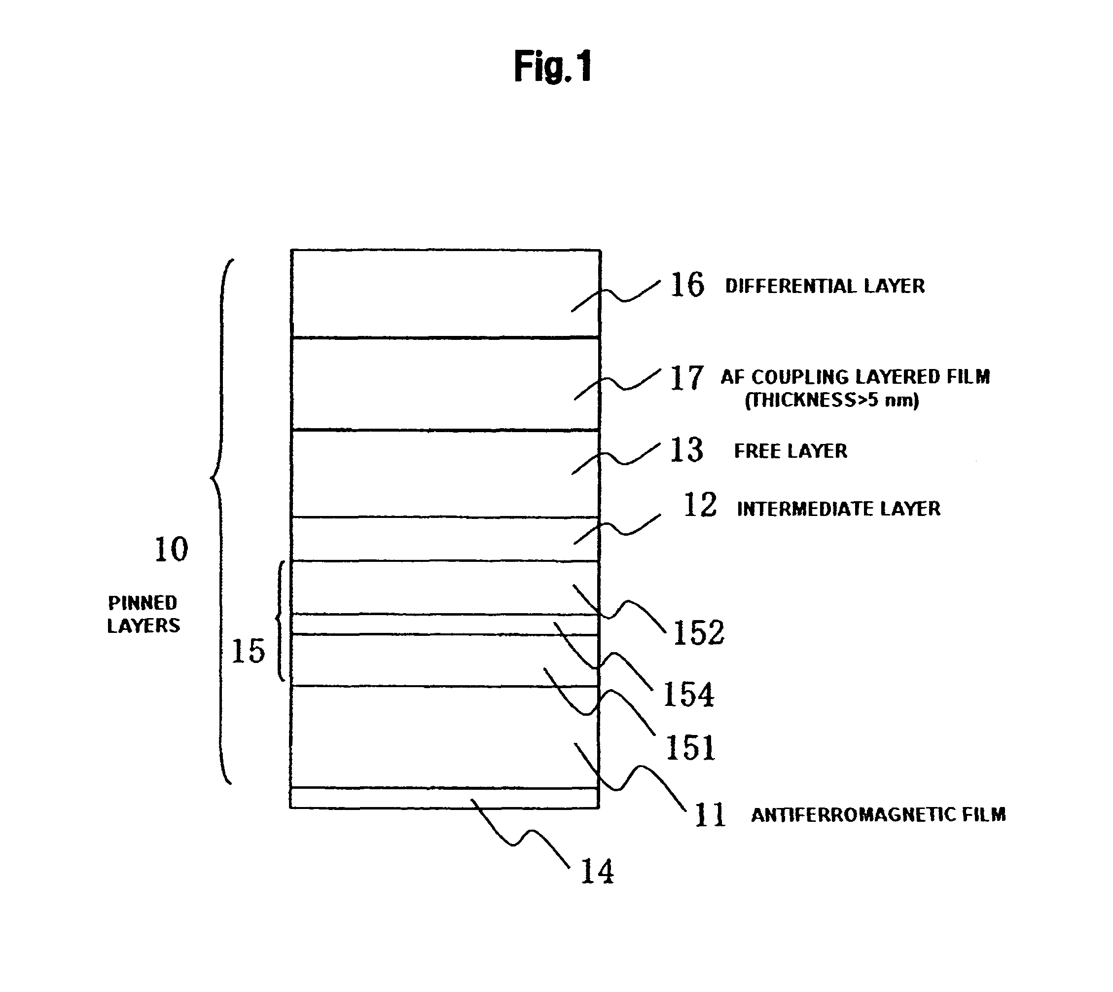
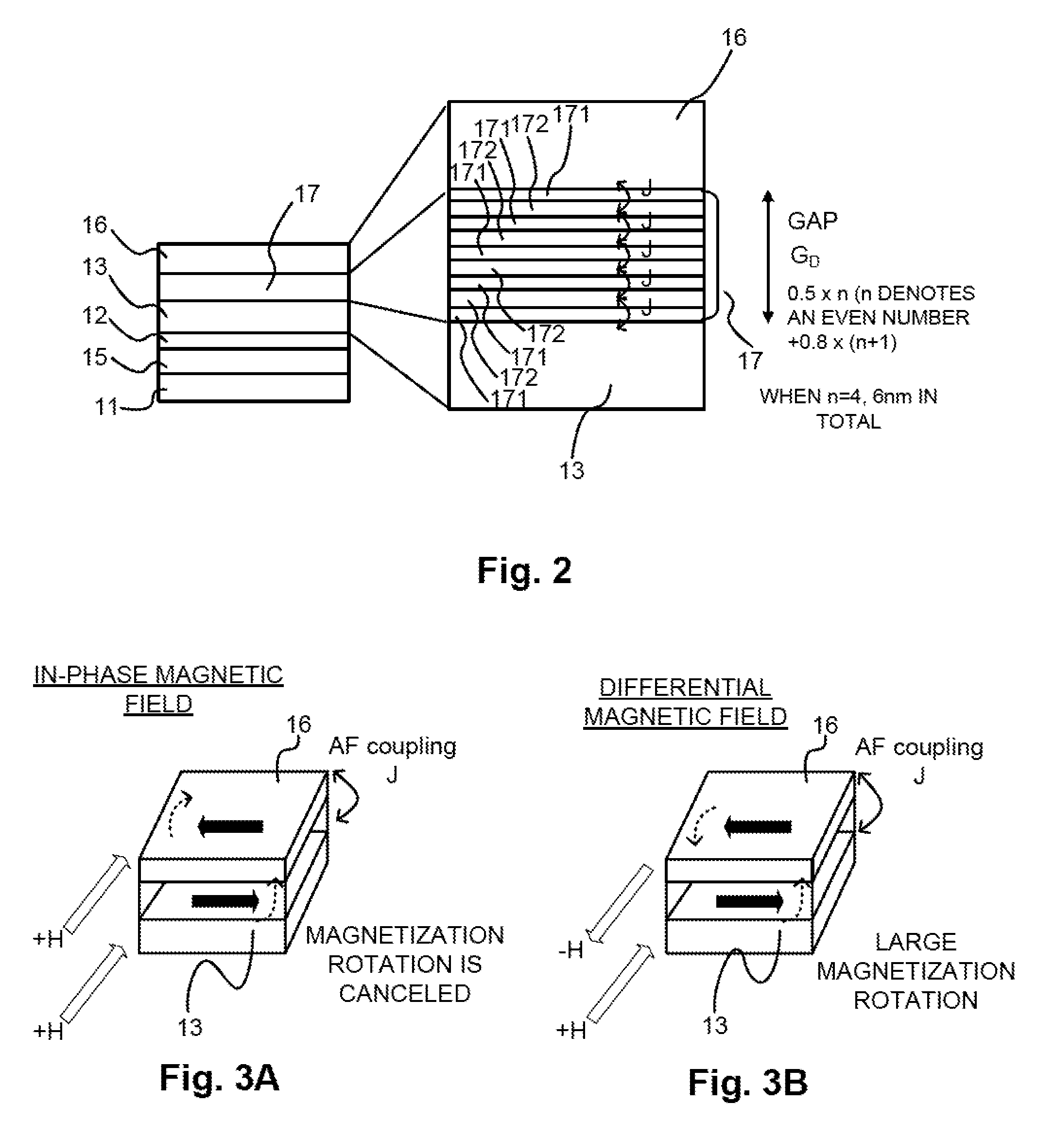
[0010]Embodiments of the present invention provide a single element type differential magnetoresistive magnetic head capable of achieving high resolution and high manufacturing stability. According to the embodiment of FIG. 1, a magnetoresistive layered film 10 is formed by stacking an underlayer film 14, an antiferromagnetic film 11, a ferromagnetic pinned layer 15, a non-magnetic intermediate layer 12, a soft magnetic free layer 13, a long distance antiparallel coupling layered film 17, and a differential soft magnetic free layer 16. The long distance antiparallel coupling layered film 17 exchange-couples the soft magnetic free layer 13 and the differential soft magnetic free layer 16 in an antiparallel state with a distance of 3 nanometers through 20 nanometers. By manufacturing the single element type differential magnetoresistive magnetic head using the magnetoresistive layered film 10, it becomes possible to achieve the high resolution and the high manufacturing stability without spoiling the GMR effect.

Problems solved by technology

In an environment in which the recording densities of magnetic recording and reproducing devices have rapidly increased, it has not been achieved to realize a magnetic recording and reproducing device having a sufficiently high recording density, in particular to realize a magnetoresistive magnetic head acting with sufficient sensitivity and outputs to the external magnetic field in the read section of the magnetic recording and reproducing device, and further to obtain a preferable characteristic with sufficiently good stability in the prior art, and it has been difficult to realize the function as a storage device.
A disadvantage of the magnetic head using the conventional magnetoresistive magnetic sensor, is that high resolution in the linear density direction is not achievable.
Although it is conceivable that the high resolution with respect to the linear density direction can be achieved by narrowing the distance between the magnetic shields, since the magnetoresistive magnetic sensor needs to be disposed in the gap of the magnetic shields, it is obvious that the gap of the magnetic shields is geometrically limited by the thickness of the magnetoresistive magnetic sensor.
Therefore, in the magnetic head using the magnetoresistive magnetic sensor of the conventional type, the magnetic shield gap has a limitation of about 25+5=30 nm because of the thickness of the magnetoresistive magnetic sensor, and even though the gap can be reduced to some extent by an effort of reducing the thicknesses of the various films, it is quite difficult to manufacture the magnetic shield gap to be narrower than 30 nm, in particular equal to or narrower than 20 nm.
The problem of the dual-element type differential magnetic head described above is difficulty in mass production as a commercial product.
This is because, due to the nature of performing the differential-operation of the two sensors to obtain one signal, the defective and variation fraction, which is double as high as that of the conventional magnetic head formed of a single sensor, should be caused.
As described above, although the high resolution must be obtained in the dual-element type differential magnetic head, since the problem in the manufacturing process is serious, it has never been realized to the market where the high recording density and high reliability have been required in recent years.

Method used


Image

  • Differential magnetoresistive magnetic head
  • Differential magnetoresistive magnetic head
  • Differential magnetoresistive magnetic head

Examples


Embodiment Construction

[0029]Embodiments of the present invention relate to a magnetic head to be mounted on a magnetic recording and reproducing device, and in particular to a differential magnetoresistive magnetic head for a high recording density magnetic recording and reproducing device.

[0030]Embodiments of the present invention have an object of providing a single element type differential magnetoresistive magnetic head capable of achieving high resolution and high manufacturing stability.

[0031]In embodiments of the present invention, there is used a magnetoresistive layered sensor film including a soft magnetic free layer, a differential soft magnetic free layer, and a long distance antiparallel coupling layered film (hereinafter simply referred also to as an antiparallel coupling layered film) for exchange-coupling the both layers in the antiparallel state with a distance of 3 through 20 nanometers. By manufacturing the single element type differential magnetoresistive magnetic head using this sens...


PUM

PropertyMeasurementUnit
thicknessaaaaaaaaaa
thicknessaaaaaaaaaa
thicknessaaaaaaaaaa

Abstract

Embodiments of the present invention help to provide a single element type differential magnetoresistive magnetic head capable of achieving high resolution and high manufacturing stability. According to one embodiment, a magnetoresistive layered film is formed by stacking an underlayer film, an antiferromagnetic film, a ferromagnetic pinned layer, a non-magnetic intermediate layer, a soft magnetic free layer, a long distance antiparallel coupling layered film, and a differential soft magnetic free layer. The long distance antiparallel coupling layered film exchange-couples the soft magnetic free layer and the differential soft magnetic free layer in an antiparallel state with a distance of about 3 nanometers through 20 nanometers. By manufacturing the single element type differential magnetoresistive magnetic head using the magnetoresistive layered film, it becomes possible to achieve the high resolution and the high manufacturing stability without spoiling the GMR effect.

Description

CROSS-REFERENCE TO RELATED APPLICATION[0001]The instant nonprovisional patent application claims priority to Japanese Patent Application No. 2007-189631 filed Jul. 20, 2007 and which is incorporated by reference in its entirety herein for all purposes.BACKGROUND OF THE INVENTION[0002]A magnetoresistive magnetic head is used as a read sensor in a high recording density magnetic recording technology including a hard disk drive as a main constituent thereof, and influences the performance of the magnetic recording technology. In an environment in which the recording densities of magnetic recording and reproducing devices have rapidly increased, it has not been achieved to realize a magnetic recording and reproducing device having a sufficiently high recording density, in particular to realize a magnetoresistive magnetic head acting with sufficient sensitivity and outputs to the external magnetic field in the read section of the magnetic recording and reproducing device, and further to ...

Claims


Application Information

Patent Timeline
Patent Type & Authority Patents(United States)
IPC IPC(8): G11B5/39
CPCB82Y10/00B82Y25/00G11B5/3929G11B2005/3996
Inventor HOSHIYA, HIROYUKIMEGURO, KENICHIHOSHINO, KATSUMISATO, YOUKATADA, HIROYUKINAKAMOTO, KAZUHIRO
Owner WESTERN DIGITAL TECH INC
Learn More