Rotary tool with an indicating coiled spring

a rotary tool and coiled spring technology, applied in the field of rotary tools, can solve the problems of inconvenient use of metal rings, metal rings with less elasticity, and weaker structure of conventional plastic rings which are sleeved on rotary tools, and achieve the effect of convenient sleev

Active Publication Date: 2012-05-15
MENG JI FEN
View PDF25 Cites 2 Cited by
  • Summary
  • Abstract
  • Description
  • Claims
  • Application Information

AI Technical Summary

Benefits of technology

[0010]The main objective of the present invention is to provide an improved rotary tool with a rotatable and replaceable indicating coiled spring which is easily sleeved on the rotary tool as being assembled.
[0012]An indicating coiled spring is able to elastically expand to be easily and co-axially sleeved on the annular groove of the tool body. The indicating coiled spring has a colored indicating mark formed thereon for easily identifying a standard of the rotary tool. The indicating coiled spring is made of metal, such that the indicating coiled spring is hard to be broken and a lifetime of the indicating coiled spring is lengthened. When operating, the indicating coiled spring is rotatable relative to the tool body. The indicating coiled spring is replaceable and re-useable.

Problems solved by technology

However, the conventional plastic ring which is sleeved on the rotary tool has a weaker structure to be easily broken after being used for a long time.
The metal ring has less elasticity and is difficult to be sleeved on the rotary tool as being assembled.
Therefore, the metal ring is inconvenient for being used as an indicating element when being attached on the rotary tool.

Method used


Image

  • Rotary tool with an indicating coiled spring
  • Rotary tool with an indicating coiled spring
  • Rotary tool with an indicating coiled spring

Examples


Embodiment Construction

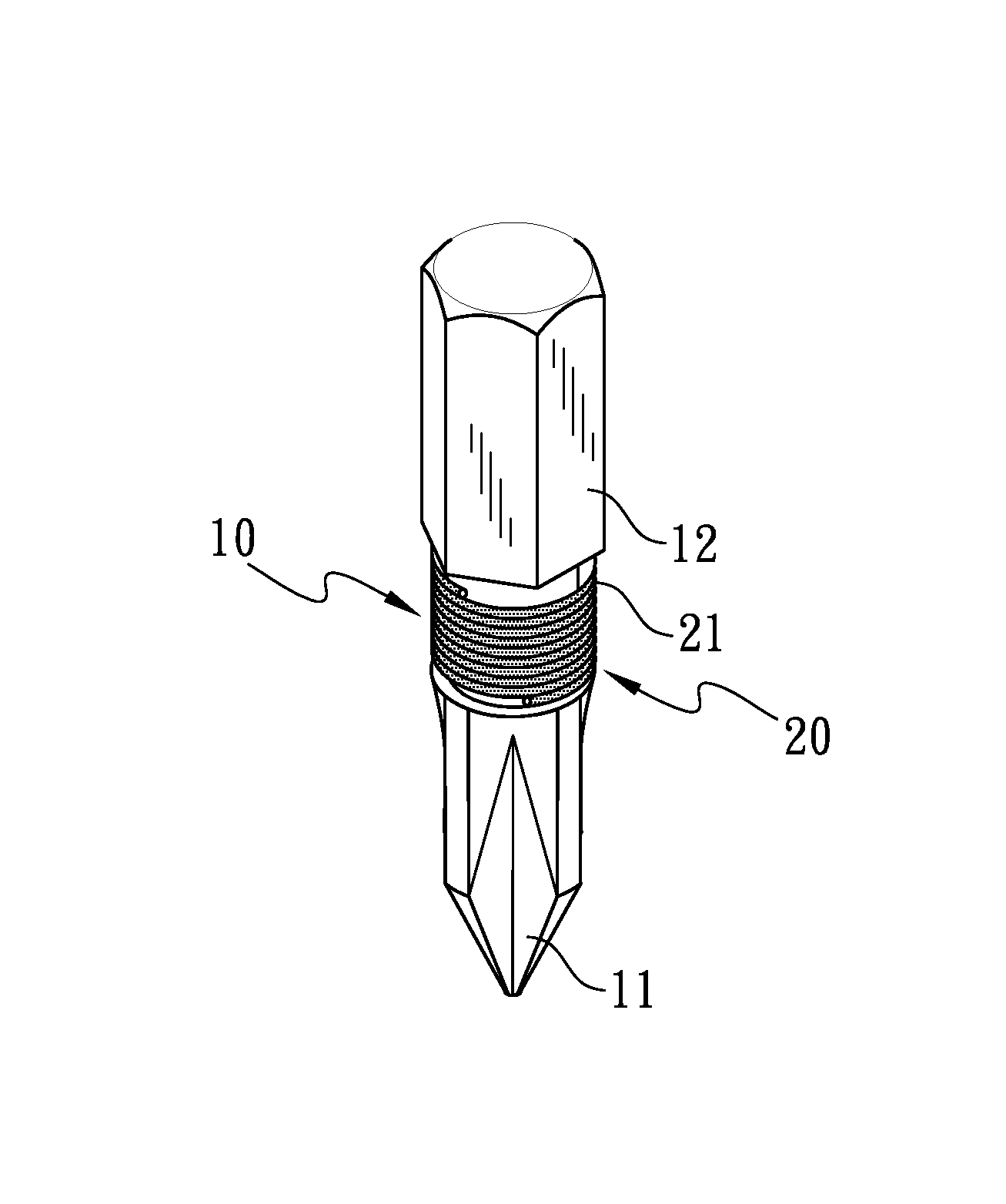
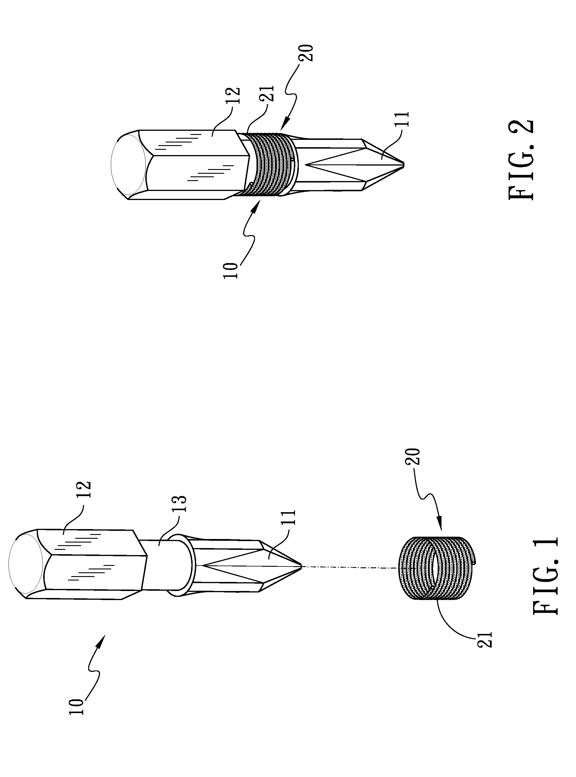
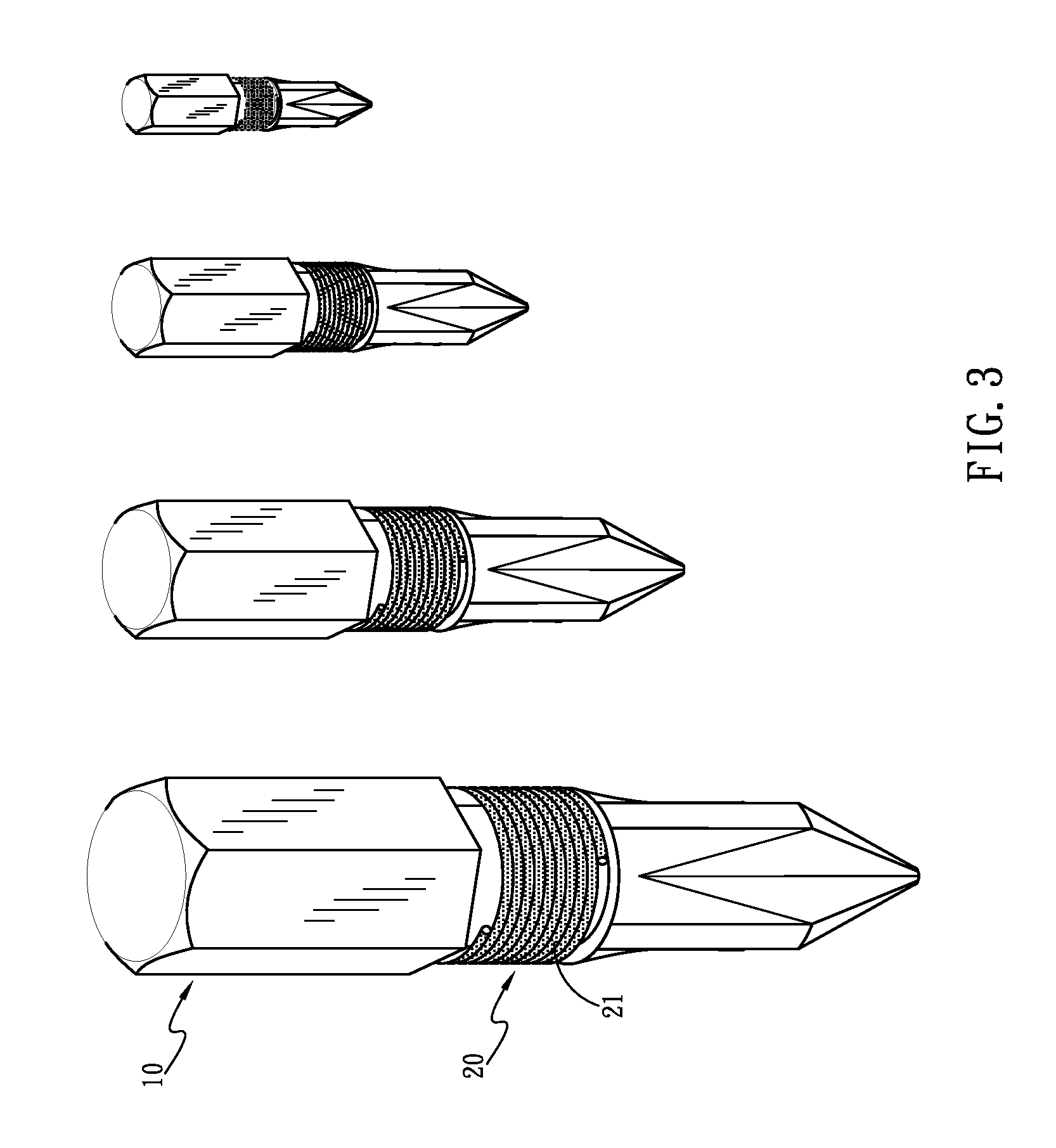
[0020]Referring to the drawings and initially to FIGS. 1-2, a first embodiment of a rotary tool with an indicating coiled spring in accordance with the present invention comprises a tool body (10) which is a screw driver bit and has a polygonal shank end (12) formed thereon. The tool body (10) has a driving end (11) integrally formed thereon opposite to the polygonal shank end (12). The driving end (11) is a flat type or a Phillips type for applying on a corresponding type screw (not shown). The tool body (10) has an annular groove (13) defined in an outer periphery of a middle thereof and located adjacent to the driving end (11).

[0021]An indicating coiled spring (20) has elasticity, such that the indicating coiled spring (20) is able to elastically expand to be easily and co-axially sleeved on the annular groove (13) of the tool body (10). When operating, the indicating coiled spring (20) is rotatable relative to the tool body (10) and stably received in the annular groove (13), su...


PUM


Abstract

A rotary tool includes a tool body having a driving end formed thereon and an annular groove defined therein. An indicating coiled spring is received in the annular groove. The indicating coiled spring has a colored indicating mark formed thereon for easily identifying a standard of the rotary tool. The indicating coiled spring is made of metal, wherein the indicating coiled spring is hard to be broken and a lifetime of the indicating coiled spring is lengthened. The indicating coiled spring is able to elastically expand to be easily and co-axially sleeved on the annular groove of the tool body, such that the indicating coiled spring being replaceable and re-useable. When operating, the indicating coiled spring is rotatable relative to the tool body.

Description

CROSS-REFERENCE TO RELATED APPLICATION[0001]This application is a Continuation-In-Part Application of Ser. No. 12 / 238,432, filed 25 Sep. 2008, and entitled “ROTARY TOOL WITH INDICATING ELEMENT”, now abandoned.BACKGROUND OF THE INVENTION[0002]1. Field of the Invention[0003]The present invention relates to a rotary tool, and more particularly to a rotary tool with a rotatable and replaceable indicating coiled spring for indicating a standard thereof.[0004]2. Description of Related Art[0005]A rotary tool, such as a screw driver bit or a socket, is often used for tightening / loosing a bolt or a screw. However, bolts and screws have various standards for providing different torsion. A user may be confused to pick up a desired tool during operating. As a result, it is necessary for a rotary tool with an indicating element to show its standard. The user would feel easy and convenient to quickly choose a rotary tool with a suitable standard.[0006]A conventional indicating element for a rotar...

Claims


Application Information

Patent Timeline
Patent Type & Authority Patents(United States)
IPC IPC(8): B25B23/00
CPCB25B13/56B25B15/001G09F3/00Y10S81/05
Inventor MENG, JI-FEN
Owner MENG JI FEN
Why Eureka
Try Eureka