Golf club grip with a hem structure

a golf club and hem structure technology, applied in the field of golf club grips, can solve the problems of difficult operation of winding strips, difficulty in unravelling, and a certain level of skill, and achieve the effect of reducing the problem of defective products

Inactive Publication Date: 2005-06-21
CHU HONG SUNG
View PDF2 Cites 86 Cited by
  • Summary
  • Abstract
  • Description
  • Claims
  • Application Information

AI Technical Summary

Benefits of technology

[0013]An object of the present invention is to provide a golf club grip including an anti-slip sheet layer which has margins hemmed and finished to prevent formation of visible clearance, thereby alleviating the problem of defective products due to the clearances formed at the marginal edges thereof.
[0014]Another object of the present invention is to provide a golf club grip with a simple construction for hemming and finishing an anti-slip sheet layer.
[0015]Still another object of the present invention is to provide a golf club grip which is not only easy to be sleeved over a golf club shaft but also is sufficiently expandable to eliminate of the problem that the grip tends to burst at its seam when being sleeved over the golf club shaft.

Problems solved by technology

However, the strip 12 or 20 is easily unravelled from the golf club shaft 14 or the inner sleeve 21 after a period of use due to insufficient adhesiveness of the glue 10 or the double-sided adhesive tape 22.
1. The operation of winding the strip 12 or 20 is difficult and requires a certain level of skill. Careful attention must be paid for conducting the winding operation. Otherwise, the strips 12, 20 can become loosened and clearances can be formed between adjacent turns of the strip 12 or 20.
2. Since the strip 12 or 20 is wound spirally, it can not provide a grip surface which is as smooth as that formed by a single-turn winding sheet wrapped around a golf club shaft. The grip surface resulting from the spirally winding strip 12 or 20 is unable to provide a good feel of comfort.
This affects adversely the appearance and quality of the golf club grip 3.
Moreover, it is difficult to sleeve the grip 3 over the golf club shaft 4 because of the insufficient extensibility of the grip 3.

Method used


Image

  • Golf club grip with a hem structure
  • Golf club grip with a hem structure
  • Golf club grip with a hem structure

Examples


first embodiment

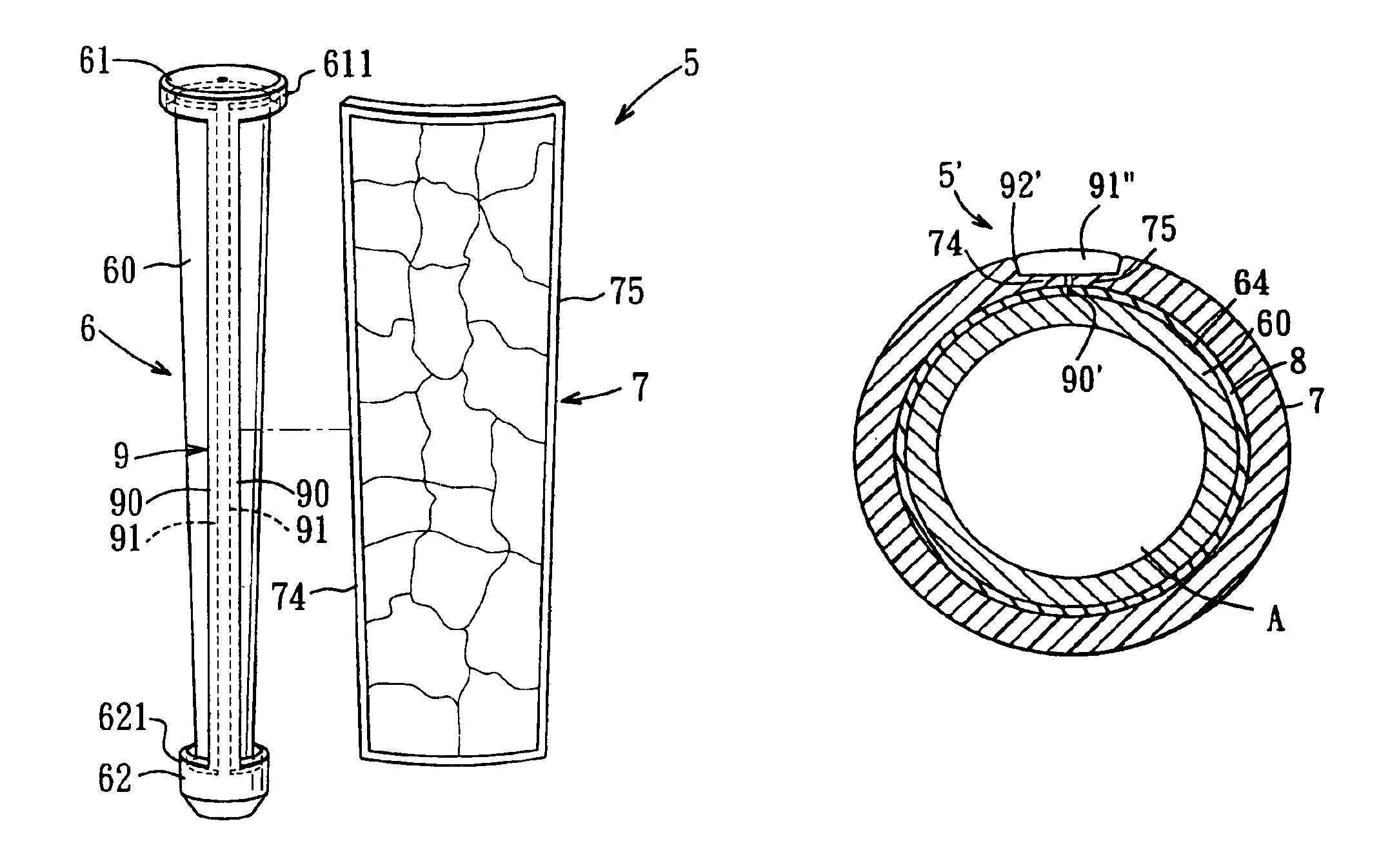
[0039]Referring to FIGS. 9 and 10, the present invention includes a golf club grip 5 mountable on one end of a golf club shaft 14. The golf club grip 5 includes an inner lining sleeve 6 and an anti-slip sheet layer 7 made of a sheeting material.

[0040]The inner lining sleeve 6 has an inner surface 63 surrounding the golf club shaft 14 and is made of a resilient polymeric material such as a rubber, a rubber compound, a thermoplastic elastomer (TPE), a thermoplastic rubber (TPR), or any suitable plastic, or a close-celled foam of a plastic or rubber. The lining sleeve material is formed into a hollow tubular body through a molding process. In particular, the lining sleeve 6 includes a sleeve body 60 with top and bottom ends respectively provided with a cap 61 and a protective rim 62. The cap 61 is annular, and projects radially from the top end of the sleeve body 60, and has a first skirt part 611 projecting downward from a peripheral end of the cap 61 and confining an annular recess 6...

fifth embodiment

[0050]Referring to FIG. 16, the hemming strip 91′ in the fifth embodiment may be prepared and assembled on the sheet layer 7 through high frequency heat cutting, hot pressing and bonding processes. In particular, a TPU or PVC sheet which is 0.15 mm-0.3 mm thick is first coated at its back side with a cement and then placed over the seam 77 and the axial margins 74, 75 of the sheet layer 7. Then, a high frequency die which is substantially U-shaped in cross section and which has axial dimensions conforming to the axial dimensions of the grip 5′ at the seam 77 is used to heat cut and hot press the TPU or PVC sheet at an instantaneous heating temperature of about 150° C. The temperature varies depending upon the sheet material and the operating machine. The hemming strip 91′ with a width of about 4 mm is therefore formed. The hemming strip 91′ is then bonded onto the outer surface of the sheet layer 7 along the seam 77 through a bonding process.

sixth embodiment

[0051]Referring to FIG. 17, the hemming strip 91″ in the sixth embodiment may be prepared and bonded to the anti-slip sheet layer 7 through a hot pressing process followed by an inset bonding process. First, the two axial margins 74, 75 of the sheet layer 7 are hot pressed to form the L-shaped corners. Then, the axial margins 74, 75 are aligned along a straight line defined the seam straightening rib 90′. The hem receiving groove 92′ is therefore formed along and above the seam straightening rib 90′, as shown in FIG. 19. The hemming strip 91″ is prepared from a sheet material with a back side thereof coated with the cement. The sheet material is hot pressed and heat cut instantaneously through a high frequency die to form a strip which has an axial length similar to the distance between the cap 61 and the protective rim 62 and which has a thickness of about 0.15-0.4 mm and a width of about 4 mm. The sheet material may be TPU, PVC or PU leather. A PU leather which is about 0.4 mm thi...


PUM


Abstract

A golf club grip includes a sleeve body having a top cap and a bottom protective rim, and an anti-slip sheet layer extending around the sleeve body between the cap and the protective rim. The sheet layer has a top circumferential margin which is hidden and hemmed by the cap. The sheet layer further includes two axial margin which extend near to each other and which are hemmed by an axial hem structure of the sleeve body. The axial hem structure extends from the cap to the protective rim to receive and hem the axial margins. As the margins of the sheet layer are hemmed and finished by the cap, the protective rim and the axial hem structure, no visible clearance is formed in the golf club grip.

Description

CROSS-REFERENCE TO RELATED APPLICATION[0001]This application claims priority of Taiwanese (patent) Application No. 091212176, filed on Aug. 7, 2002.BACKGROUND OF THE INVENTION[0002]1. Field of the Invention[0003]The invention relates to a golf club grip, more particularly to a golf club grip having a hem structure for finishing and hemming the marginal edges of a winding sheet layer.[0004]2. Description of the Related Art[0005]Referring to FIGS. 1 and 2, a conventional golf club grip 1 includes a fabric lining 11 adhered by means of a natural fixative 10 to a golf club shaft 14, a longitudinal leather strip 12 spirally wrapped around the lining 11, and two coiled wires 13 respectively fastening top and bottom ends of the strip 12 to the golf club shaft 14.[0006]FIG. 3 shows a conventional golf club grip 2 disclosed in U.S. Pat. No. 6,386,989, which includes a winding strip 20 made of a synthetic leather, such as polyurethane, and an inner sleeve 21. The strip 20 is spirally wound ar...

Claims


Application Information

Patent Timeline
Patent Type & Authority Patents(United States)
IPC IPC(8): A63B53/14
CPCA63B53/14A63B60/08A63B60/14
Inventor CHU, HONG-SUNGWU, CHIA-HUNG
Owner CHU HONG SUNG
Why Eureka
Try Eureka