Corrugated cable co-axial connector

a coaxial connector and corrugated cable technology, applied in the direction of coupling device connection, coupling contact member, coupling device details, etc., can solve the problems of easy damage to the spring ring, inconvenient installation on site, falling off, etc., to ensure the radial clamping force, reduce the elasticity of the annular elastic clip, and ensure the connection

Active Publication Date: 2019-08-27
COMMSCOPE TECH LLC
View PDF26 Cites 2 Cited by
  • Summary
  • Abstract
  • Description
  • Claims
  • Application Information

AI Technical Summary

Benefits of technology

[0021]In the corrugated cable co-axial connector according to embodiments of the present invention, the annular elastic clip is driven by the threaded connection to generate radial elastic deformation to lock the corrugated cable, so that the radial clamping force of the annular elastic clip mainly comes from the interference fit between the connector body and the annular elastic clip rather than the elasticity of the annular elastic clip, which ensures that even if the elasticity of the annular elastic clip is reduced by repeated assembly and disassembly of the connector, sufficient radial clamping force can still be applied to the annular elastic clip via the threaded connection to reliably lock the corrugated cable. Therefore, the corrugated cable co-axial connector according to embodiments of the present invention is suitable for repeated use.
[0022]In the corrugated cable, co-axial connector according to embodiments of the present invention, the elastic clip structure is combined with the elastic ring structure, and the axial pre-tightening force is applied to the clamping nut by the elastic ring, so that the thread locking between the clamping nut and the connector body is unlikely to become loose. Therefore, the connector body can reliably provide the radial clamping force to the annular elastic clip to ensure a reliable connection between the connector and the corrugated cable.
[0023]The elastic ring in the corrugated cable co-axial connector according to embodiments of the present invention can be easily sleeved on the annular elastic clip, and the annular elastic clip, the elastic ring and the clamping nut are adapted to being connected together to be provided to a user as a complete assembly, so that the user can install the elastic ring on the connector without wasting labor, and the corrugated cable can be connected to the connector just by the simple thread fit between the connector body and the clamping nut. Therefore, the corrugated cable co-axial connector according to the embodiments of the present invention is simple to manufacture and is convenient to use.

Problems solved by technology

During the use of the connector adopting the spring ring structure, onsite installation is inconvenient, as the cable needs to be installed on the connector by using a special torque wrench.
In addition, when the connector is repeatedly disconnected, the spring ring is damaged easily, and may even fall off.

Method used


Image

  • Corrugated cable co-axial connector
  • Corrugated cable co-axial connector
  • Corrugated cable co-axial connector

Examples


Embodiment Construction

[0032]Various embodiments of the present invention will now be described in detail by way of example only.

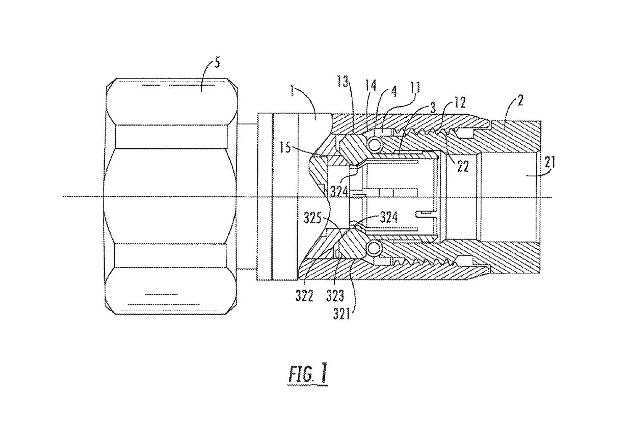
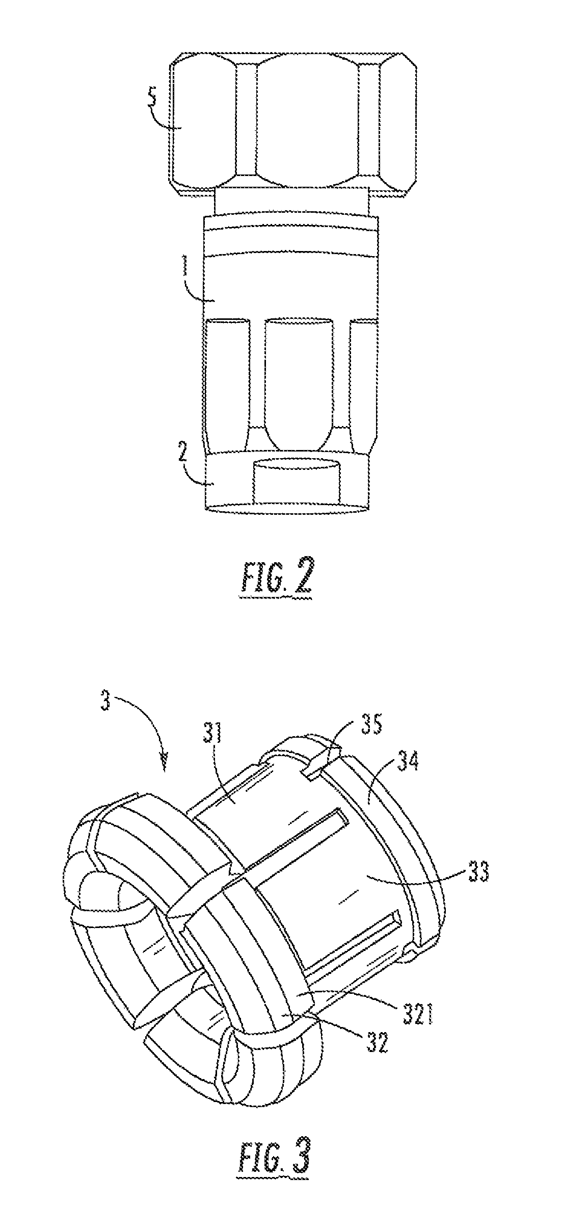
[0033]Referring to FIG. 1 and FIG. 2, show a section view of a corrugated cable co-axial connector according to an embodiment of the present invention. The corrugated cable co-axial connector includes: a connector body 1 having a connector through hole 11, and having an interface end and a matching end in an axial direction of the connector through hole 11 which are opposite each other. The connector through hole 11 of the connector body 1 penetrates through the whole connector body 1 to at least allow an inner conductor 101 of a corrugated cable 10 to extend in the connector through hole 11 to an interface end. The connector body 1 has an internal thread 12 at the matching end, and an interface structure is arranged at the interface end of the connector body 1 to lock the connector body 1 to an external port. For example, the interface structure is a connecting nut 5 as shown i...


PUM


Abstract

The corrugated cable co-axial connector includes a connection body (1), having an internal thread (12) in a connector through hole (11); a clamping nut (2), having a central through hole (21), having a cable end and a clamping end in an axial direction of the central through hole (21) which are opposite to each other, and having an external thread (22) at the clamping end; an annular elastic clip (3) which is axially slidingly fitted into the central through hole (21) of the clamping nut (2); and a resilient ring (4) sleeved around the annular elastic clip (3) and located between the clamping end of the clamping nut (2) and the annular elastic clip (3). When a corrugated cable (10) having a corrugated outer conductor (102) is received in the central through hole (21) of the clamping nut (2), the connector body (1) applies at least a radial inward force to the annular elastic clip (3) by the engagement of the external thread (22) and the internal thread (12), to lock the corrugated cable (10) in the annular elastic clip (3). The connector is simple to manufacture and is convenient to use. At the same time, it is able to ensure the reliable cable connection and is suitable for repeated use.

Description

RELATED APPLICATION[0001]This application claims priority from Chinese Application No. 201710135453.9 filed Mar. 8, 2017, the disclosure of which is hereby incorporated herein in its entirety.FIELD OF THE INVENTION[0002]Embodiments of the present invention relate to a corrugated cable co-axial connector, and in particular to a radio frequency device connector for an annular corrugated outer conductor cable.BACKGROUND OF THE INVENTION[0003]A radio frequency device connector (also referred to as a radio frequency connector) for annular corrugated outer conductor cables is an electromechanical assembly which connects a conductor (wire) with a suitable mating device to turn on and turn off microwave signals. In existing communication products, the radio frequency signal transmission between the commonly used radio remote unit (Radio Remote Unit, RRU) and a smart antenna is typically achieved with a ½ radio frequency co-axial cable in general, with co-axial radio frequency connectors ins...

Claims


Application Information

Patent Timeline
Patent Type & Authority Patents(United States)
IPC IPC(8): H01R9/05H01R24/56H01R103/00
CPCH01R4/4809H01R4/489H01R9/0521H01R9/0527H01R13/02H01R13/502H01R24/40H01R2201/02H01R24/564H01R2103/00H01R9/0524
Inventor LIU, JINWU, JIANPINGZHANG, YUJUN
Owner COMMSCOPE TECH LLC
Why Eureka
Try Eureka