
Tone noise reduction in turbomachines

a turbomachine and tone noise technology, applied in machines/engines, liquid fuel engines, instruments, etc., can solve the problems of many individual noise sources, tone noise is produced, and the fan is typically a major source of tone noise, so as to achieve the effect of reducing the tone noise emanating from the turbomachine and improving the attenuation

Active Publication Date: 2012-05-15
ROLLS ROYCE PLC
View PDF14 Cites 54 Cited by
  • Summary
  • Abstract
  • Description
  • Claims
  • Application Information

AI Technical Summary

Benefits of technology

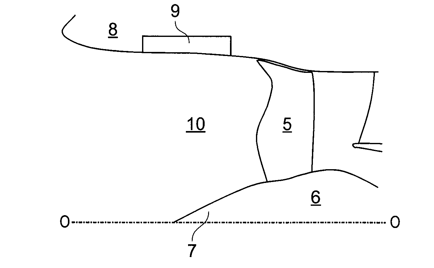
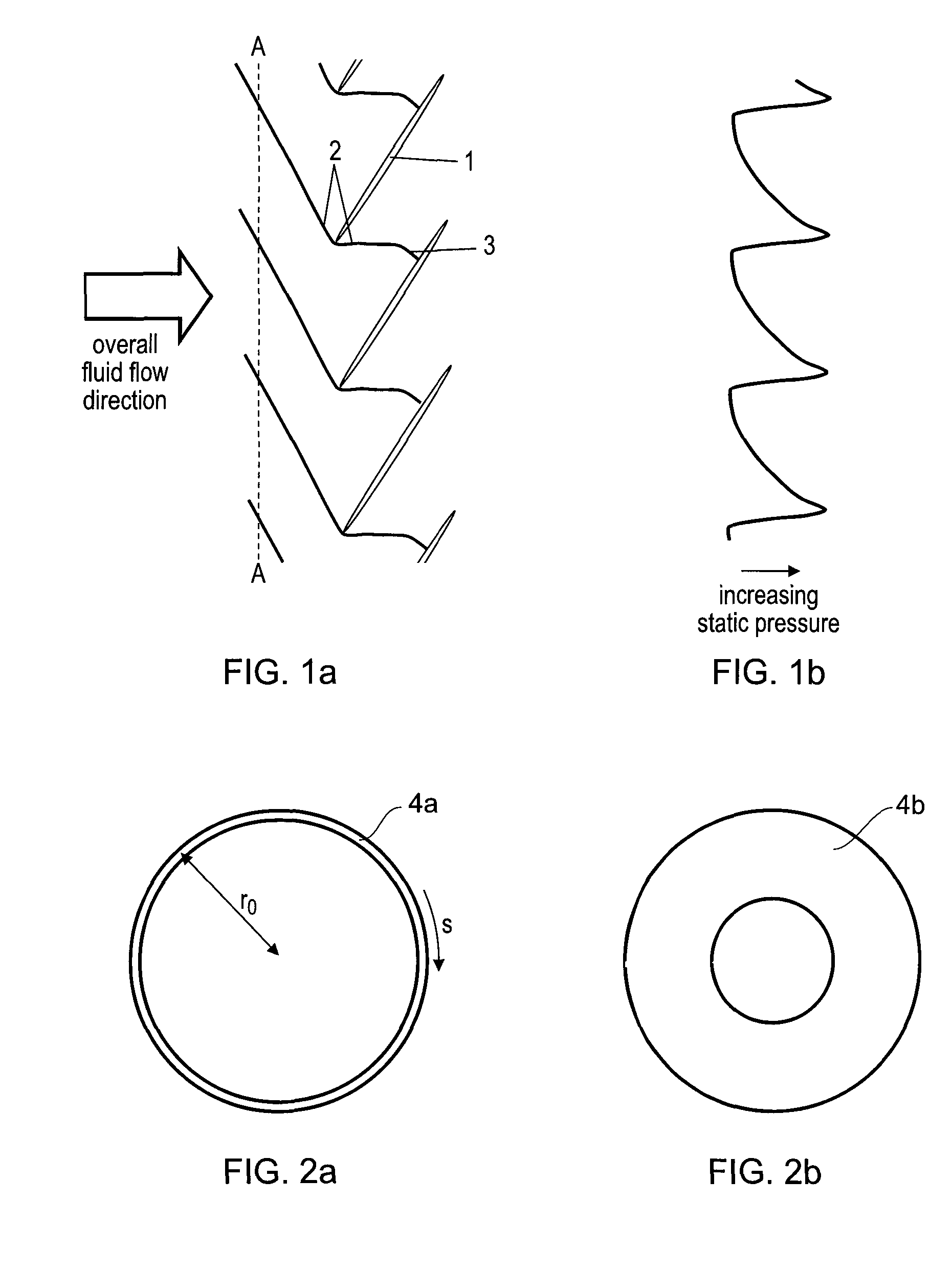
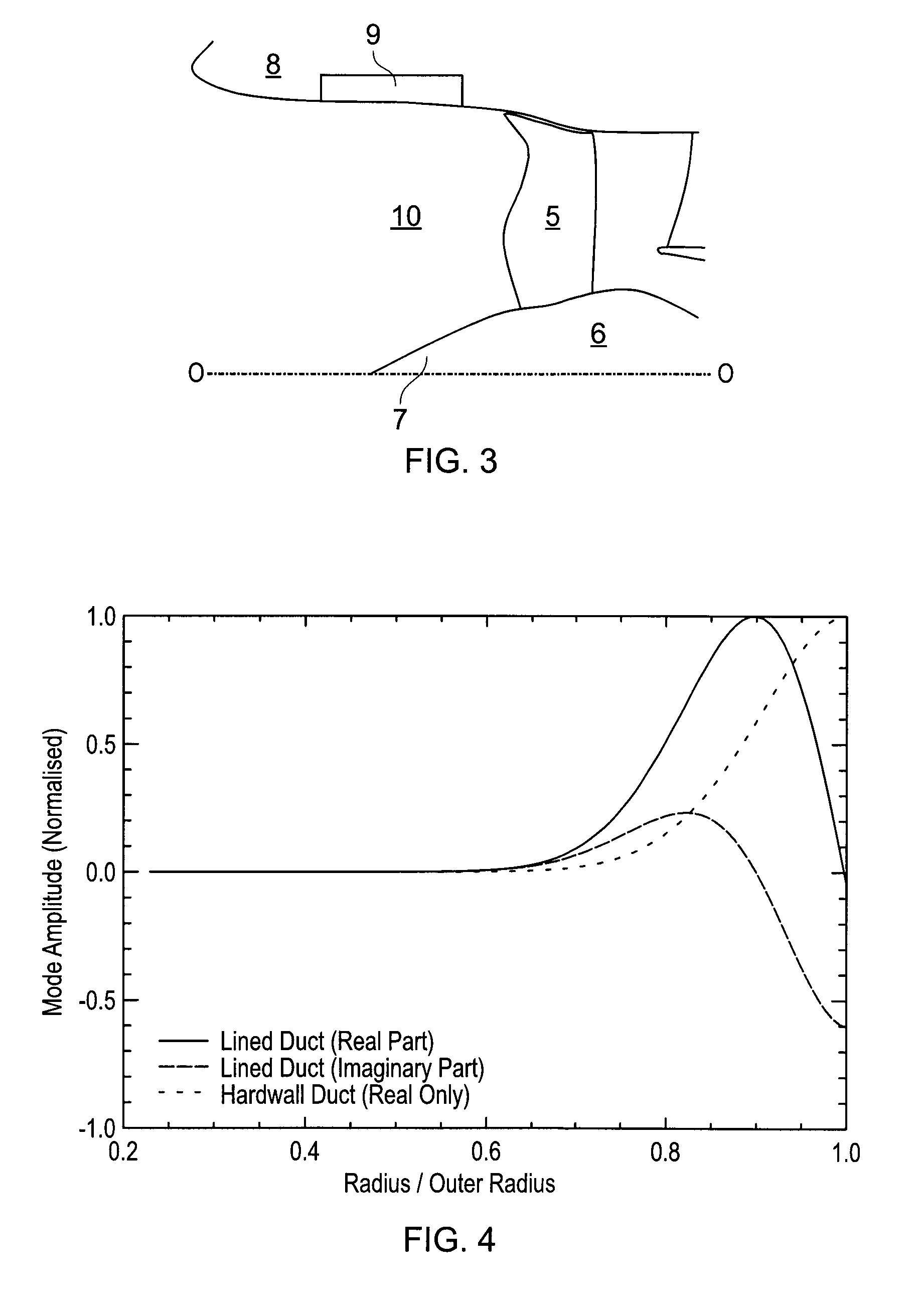
[0016]The present invention is at least partly based on the inventors' insight that tone noise emanating from a turbomachine can be reduced by directing acoustic power into those acoustic modes which are better attenuated by the machine itself. A further insight of the inventors was that this can be achieved by careful control of the blade leading edge position with spanwise distance.

Problems solved by technology

The noise produced by an aero gas turbine engine is the accumulation of many individual noise sources.
The fan is typically a major source of tone noise emanating from the inlet, particularly when the engine is at an operating condition which generates supersonic fluid flow at the fan blades.
In this case, tone noise is produced by shock waves emanating from the fan blades and propagating upstream through the engine intake.
Although buzz can be the predominant part of the tone noise produced by a fan, it is effectively a distortion of the BPF tone and its harmonics.

Method used


Image

  • Tone noise reduction in turbomachines
  • Tone noise reduction in turbomachines
  • Tone noise reduction in turbomachines

Examples


Embodiment Construction

[0146]The invention will now be described in detail with reference to examples and embodiments.

[0147]FIG. 6 is a high level flow chart showing stages in a fan blade design process which has the aim of reducing fan tone noise at an operating condition which generates supersonic fluid flow at the blades.

[0148]A first stage 11 is the determination of the pressure field produced at the operating condition in the engine intake upstream of the blade relative to the overall direction of fluid flow through the turbomachine.

[0149]An initial task in this stage is, typically, to parametrise the blade geometry so that later it is possible to introduce variations to that geometry. For the purposes of fan tone noise optimisation, the shape of the fan blade leading edge is expected to be a dominant factor, so one approach is to vary the shape of the leading edge of the fan blade, while maintaining the trailing edge shape and the general aerodynamic design of the fan blade.

[0150]To assess the fan t...


PUM


Abstract

A blade for a turbomachine extends in use, in a radial direction relative to the axis of the turbomachine. The turbomachine has at least one operating condition which generates supersonic fluid flow at the blade. The blade is adapted to provide, at the supersonic operating condition, a leading edge sweep angle which varies such that successive radial positions (i) to (iii) along the leading edge are at respective sweep angle turning points. Position (i) is the radially inner and position (iii) the radially outer of the positions. Position (i) is at or radially outward of the 30% span position, where 0% span is the radially innermost point of the leading edge and 100% span is the radially outermost point of the leading edge.

Description

FIELD OF THE INVENTION[0001]The present invention relates to blades for a turbomachine, turbomachines including a casing and a cascade of circumferentially spaced blades, and methods of designing and producing blades. In particular, although not exclusively, the blades may be fan blades and the turbomachines may be aero gas turbine engines.BACKGROUND OF THE INVENTION[0002]The significance of acoustics in the design of aero gas turbine engines has increased in recent years as a consequence of stringent requirements imposed by regulatory authorities on the noise radiated during particularly the take-off and approach phases of flight.[0003]The noise produced by an aero gas turbine engine is the accumulation of many individual noise sources. Sources related to the turbomachinery (fan, turbine, compressor) contain both broadband and tonal components, while the jet noise source is broadband in nature.[0004]The fan is typically a major source of tone noise emanating from the inlet, particu...

Claims


Application Information

Patent Timeline
Patent Type & Authority Patents(United States)
IPC IPC(8): F04D21/00
CPCF01D5/141F02K3/06F04D21/00F04D29/324F05D2240/121F05D2240/303Y02T50/673F05D2260/96F05D2250/184Y02T50/60
Inventor WILSON, ALEXANDER GEORGESTIEGER, RORY DOUGLASSMITH, NIGELCOUPLAND, JOHN
Owner ROLLS ROYCE PLC
Learn More