Inductive proximity sensor for embedded mounting and method of design

a technology mounting plate, which is applied in the field of inductive proximity sensor, can solve the problems of increasing the impact of eddy current loss in the mounting plate on the total amount of eddy current loss, attenuating the oscillator, and ordinary long range sensors not fully embeddable in steel mounting plates, so as to improve the embeddability of proximity sensors without adversely affecting their sensor rang

Inactive Publication Date: 2012-05-15
OPTOSYS SA
View PDF5 Cites 12 Cited by
  • Summary
  • Abstract
  • Description
  • Claims
  • Application Information

AI Technical Summary

Benefits of technology

[0024]It is an object of the present invention to improve the embeddability of proximity sensors without adversely affecting their sensor range.

Problems solved by technology

The power loss caused by these eddy currents represents a load which increasingly attenuates the oscillator as the distance between the sensor and the target is reduced.
The greater the target distance, the smaller are the eddy current losses in the target, resulting in an increased impact of eddy current losses in the mounting plate on the total amount of eddy current losses which is determining for the oscillator attenuation.
Ordinary long range sensors are not fully embeddable in a steel mounting plate because the attenuation caused by the mounting plate in the embedded state almost coincides with or exceeds the reference threshold of the sensor, rendering in particular any switching type proximity sensor inoperable.

Method used


Image

  • Inductive proximity sensor for embedded mounting and method of design
  • Inductive proximity sensor for embedded mounting and method of design
  • Inductive proximity sensor for embedded mounting and method of design

Examples


Embodiment Construction

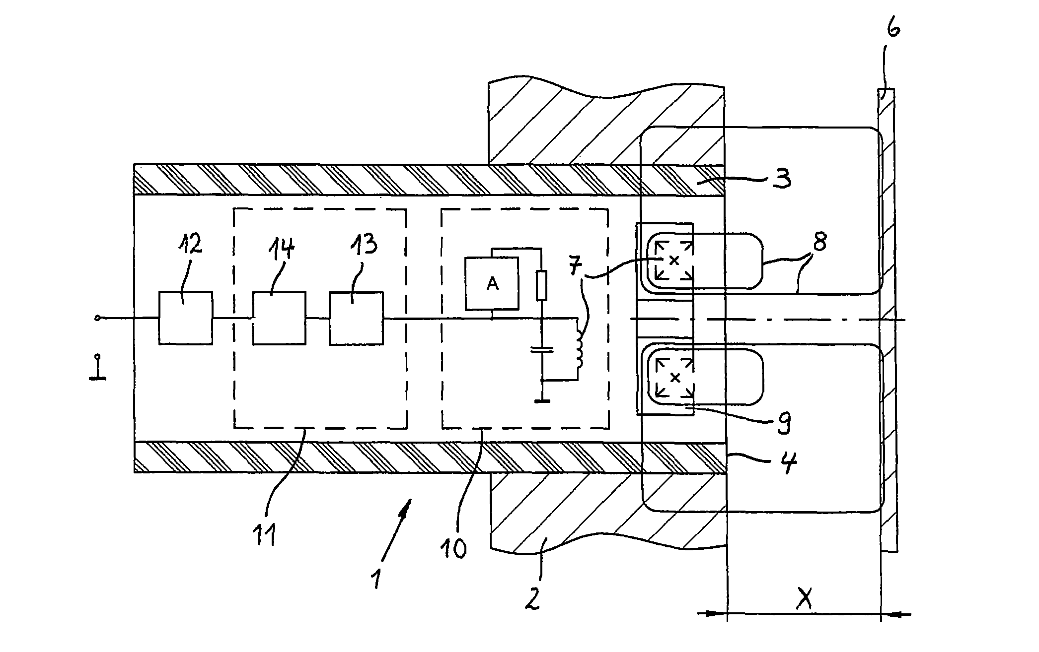
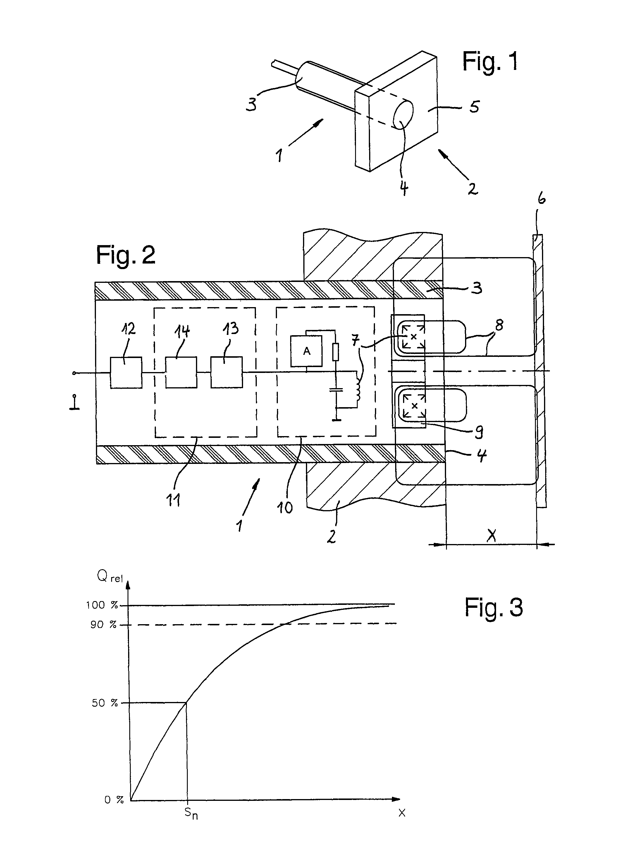
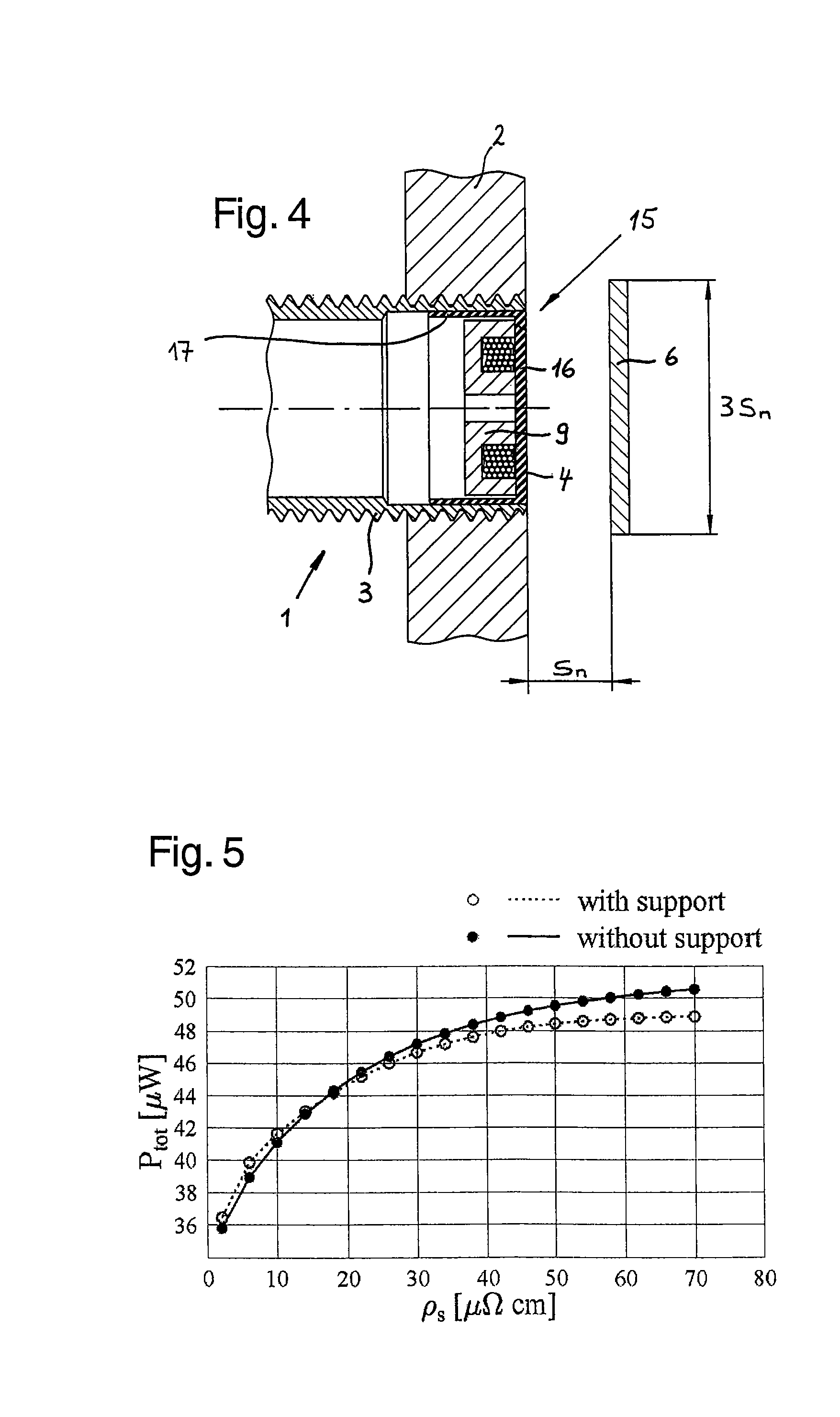
[0034]FIG. 1 shows an inductive proximity sensor 1 mounted in a mounting plate 2. The enclosure of the sensor substantially consists of a cylindrical sleeve 3 made of non-ferromagnetic metal, which is threaded on its outside and screwed into a correspondingly threaded through-bore of the mounting plate 2, so that a sensing face 4 of the enclosure, which is perpendicular to the sleeve axis, is flush with a front surface 5 of the mounting plate 2. The term flush mounted is used as a synonym for embedded hereinafter and implies that the bore through the mounting plate is not enlarged near the front surface 5 of the mounting plate, so that no space is provided around a front portion of the sensor 1.

[0035]FIG. 2 is a schematic representation of an arrangement comprising an inductive proximity switch 1 mounted in a mounting plate 2 according to FIG. 1 and a target plate 6 arranged in front of its sensing face 4. The sensor has an electrical circuit and a magnetic circuit, which are repres...


PUM


Abstract

The invention relates to an inductive proximity sensor for embedding in a mild steel mounting plate, comprising an enclosure with a front wall of synthetic material forming a sensing face at a front end of the enclosure, an oscillator comprising a sensor coil with a core made of a material with a relative magnetic permeability larger than 1, typically a ferrite, which is arranged within the enclosure behind the front wall so that an open side of the core is directed towards the sensing face in order to direct the magnetic field of the coil towards a target in front of the sensing face, a hollow cylindrical metal member arranged perpendicular to the sensing face and surrounding the core, and a measuring circuit for measuring an attenuation of the oscillator due to eddy currents. The core is radially surrounded by a metal layer with a low electrical resistivity of less than 15 μΩ·cm and with a thickness of less than 40 μm, in order to improve the embeddability of the sensor. Alternatively, this thin metal layer may be omitted, if the electrical resistivity of the metal member is adjusted to a value in the range of 15 μΩ·cm-50 μΩ·cm.

Description

BACKGROUND OF THE INVENTION[0001]The invention relates to an inductive proximity sensor for embedding in a metal mounting plate and a method of designing the same.[0002]The proximity sensors comprise an RLC oscillator with a sensor coil, the magnetic field of which generates eddy currents in a target. The power loss caused by these eddy currents represents a load which increasingly attenuates the oscillator as the distance between the sensor and the target is reduced.[0003]The measure for the rate at which an oscillator dissipates its stored energy is the quality factor Q, which is 2π times the ratio of the energy stored to the energy dissipated per cycle. The maximal quality factor Qmax of the oscillating system of an inductive proximity sensor is measured in the sensor's non-embedded state and in absence of the target. In operation, the quality factor Q depreciates due to eddy current losses in the mounting plate and / or in a target. Normalizing the quality factor Q to the maximal ...

Claims


Application Information

Patent Timeline
Patent Type & Authority Patents(United States)
IPC IPC(8): G01R33/00
CPCH03K17/9502H03K17/9547H03K17/9505
Inventor DE HUU, MARCHEIMLICHER, PETERRH ME, CHARLESVENIER, PHILIPPE
Owner OPTOSYS SA
Why Eureka
Try Eureka