
Knitting tool

a technology of knitting and catching rod, which is applied in the field of knitting tools, can solve the problems of partially or completely releasing the catching rod

Active Publication Date: 2012-05-22
GUSTAV SELTER
View PDF22 Cites 20 Cited by
  • Summary
  • Abstract
  • Description
  • Claims
  • Application Information

AI Technical Summary

Benefits of technology

[0015]Such bayonet catches provide a reliable and permanent connection that can be released again merely be a press and turn movement exerted with force application.
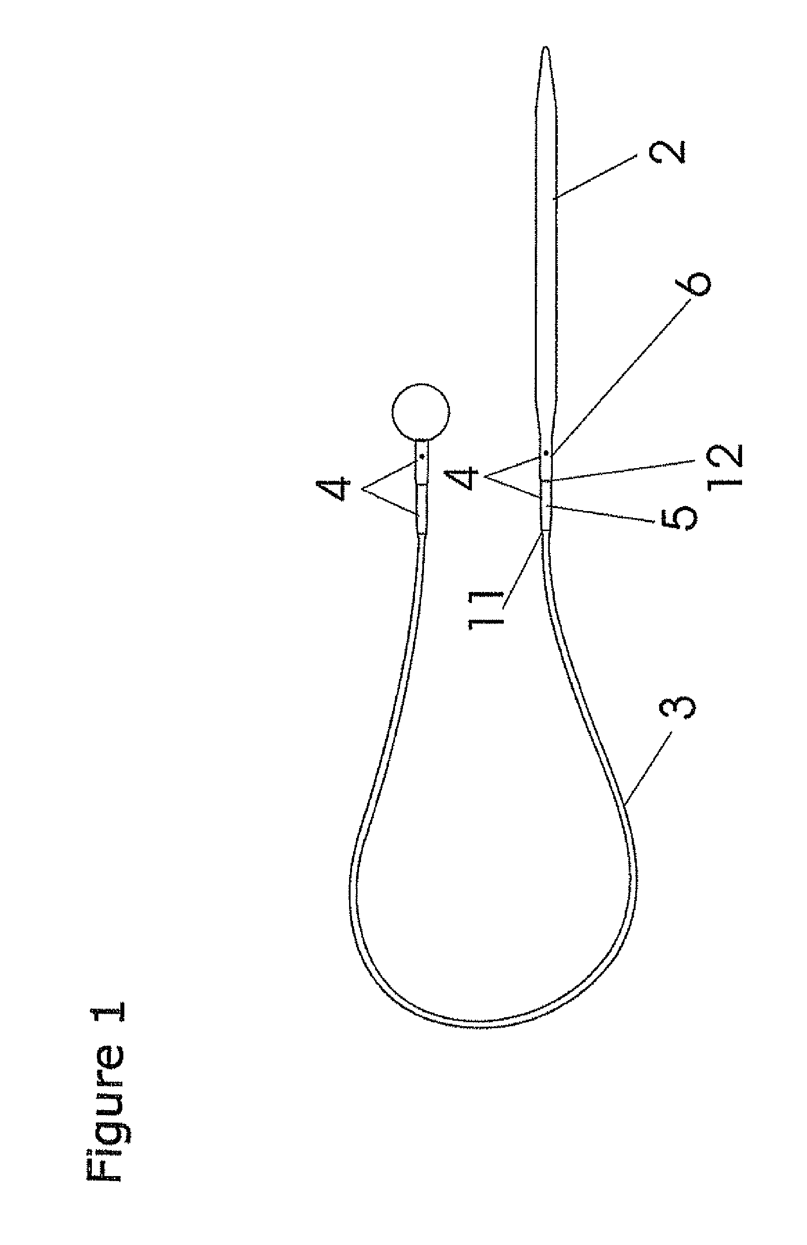
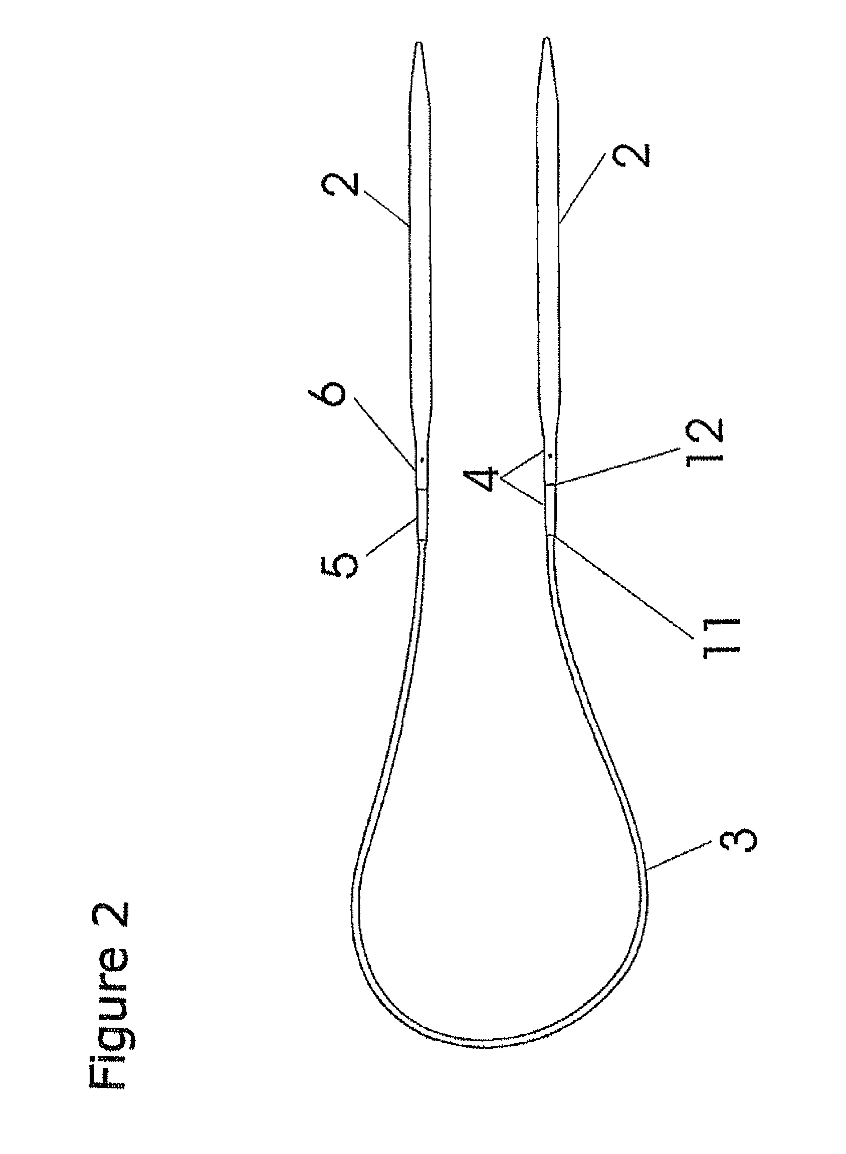
[0018]A particular advantage is that the knitting tool according to the invention can be configured both in the form of a single knitting needle or can also be configured as a circular knitting needle with two knitting points and a flexible cord joining these to hold the stitches of the knitted product.
[0019]In an ergonomic configuration, the knitting tool according to the invention can be bent off in an area behind the conically extending end region of the knitting point. This is particularly important if the knitting tool is used for knitting cylindrical handwork with a relatively small diameter. Indicated here by way of example is a bend in the transition area between the knitting point and the flexible cord of a circular knitting needle, as a result of which the freedom of movement of the two knitting points of the circular knitting needle relative to one another is assisted.

Problems solved by technology

A disadvantage of these knitting tools is that the catches can be partially or completely released during the knitting process by the unavoidable movement of the knitting tool and the resulting vibrations, and as a result of this either the stitches become caught on the partially released catches or the stitches fall off the knitting tool at the completely released catches.

Method used


Image

  • Knitting tool
  • Knitting tool
  • Knitting tool

Examples


Embodiment Construction

[0030]FIG. 1 shows an exemplary embodiment of the knitting tool 1 according to the invention in the form of a single knitting needle with a conically tapering knitting point 2 in its end region and a flexible cord 3 for holding the stitches of the knitted product. The knitting point 2 is releasably joined to the flexible cord 3 by means of a coupling device 4. The coupling device 4 has at least two elements that can be coupled. The elements that can be coupled comprise a plug element 5 and also a socket element 6. The plug element 5 and the socket element 6 are firmly engaged with one another (locked in place) by means of a bayonet catch.

[0031]In a preferred embodiment, one plug element 5 of the flexible cord is provided with a coupling element 13, e.g. in the form of a ball or other suitable body, in which the diameter is larger than the diameter of the flexible cord. This coupling element 13 can be fastened to the flexible cord instead of a further knitting point and has the same ...


PUM


Abstract

The present invention relates to a knitting tool 1 in which a knitting point 2 is joined to a flexible cord 3 for holding the knitted product, wherein the knitting point 2 and the flexible cord 3 are joined to one another by means of a coupling device 4 and the coupling device 4 has at least two elements 5, 6 that can be releasably coupled to one another by means of a bayonet catch.

Description

BACKGROUND OF THE INVENTION[0001]1. Field of the Invention[0002]The present invention relates to a knitting tool, in which a knitting point is joined to a flexible cord for holding the knitted product by means of a bayonet catch, which enables knitting points of different needle thickness to be combined in an instant with cords of different length and to be repeatedly reconfigured as desired.[0003]2. Discussion of Background Information[0004]Knitting needles consisting of two knitting points joined by a flexible central part are generally known by the term circular knitting needle. Circular knitted goods of larger diameter are worked by means of circular knitting needles. The total length of a circular knitting needle is dependent on the dimensions of the knitted product and usually ranges between approximately 40 cm and 120 cm. Besides their length, circular knitting needles are primarily characterised by the diameter of the knitting points. A quite specific diameter is necessary d...

Claims


Application Information

Patent Timeline
IPC IPC(8): D04B35/02
CPCD04B3/02
Inventor SELTER, THOMAS
Owner GUSTAV SELTER
Learn More