Device for the pivoting connection of a wiper blade to a wiper arm of a windscreen wiper
What is Al technical title?
Al technical title is built by PatSnap Al team. It summarizes the technical point description of the patent document.
a technology of windscreen wiper and wiper blade, which is applied in the direction of vehicle maintenance, vehicle cleaning, domestic applications, etc., can solve the problem of residual water being drawn back onto the already cleaned vehicle window
Inactive Publication Date: 2012-05-29
ROBERT BOSCH GMBH
View PDF8 Cites 35 Cited by
Summary
Abstract
Description
Claims
Application Information
AI Technical Summary
This helps you quickly interpret patents by identifying the three key elements:
Problems solved by technology
Method used
Benefits of technology
[0006]The open longitudinal side of the connecting element is thus sealed by the associated longitudinal wall of the adapter. The open longitudinal side of the connecting element makes it possible to easily actuate the clip elements of the adapter during disassembly. In addition, the device in accordance with the invention makes possible a connection of the wiper arm to the wiper blade that is favorable in terms of the airflow, in particular in the area of the upper cover wall and the front wall of the connecting element that faces away from the wiper arm. These areas are particularly critical during the downward movement of the windshield wiper, when, because of the inflowing air, there is a risk that residual water will be drawn back onto the already cleaned vehicle window. This can be counteracted because of the free scope of design in the case of the inventive device. As a result, blind angles where residual water can accumulate when it rains are expediently avoided. Furthermore, it is expedient if a spoiler element is provided, which, for one, supports the spoiler effect of a wiper blade spoiler, and, secondly, directs the airflow in this region away from the vehicle window so that water being carried along by the airflow cannot make impact with the vehicle window.
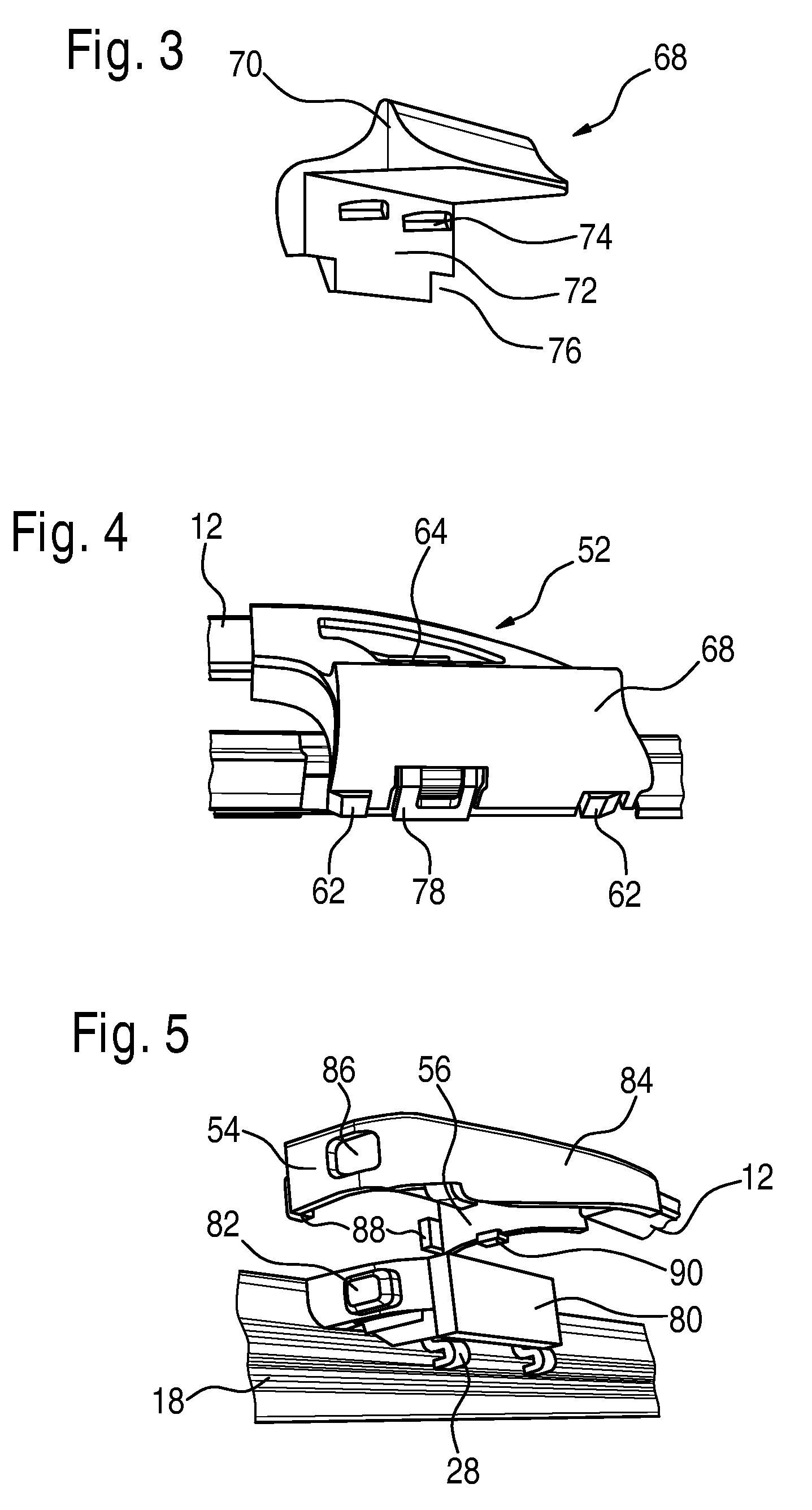
[0008]In addition to the designer function, the protective cap can perform hydrodynamic functions and safety tasks. In the first case, it overlaps at least partially the cover wall of the connecting element, whereby the overlapping part of the protective cap is embodied as a spoiler element or supports a separate spoiler element. As a result, the spoiler function of the wiper blade spoiler is supported and the air stream is deflected from the vehicle window in the area of the inventive device. This prevents (or at least reduces) water from being drawn back onto the already cleaned vehicle window during the downward movement of the windshield wiper. If the lateral wall of the protective cap is fastened to the adapter, which it simultaneously uses as a securing bow, which holds the adapter and the connecting element together.
Problems solved by technology
These areas are particularly critical during the downward movement of the windshield wiper, when, because of the inflowing air, there is a risk that residual water will be drawn back onto the already cleaned vehicle window.
Method used
Image
Click on the blue label to locate the original text in one second.
Reading with bidirectional positioning of images and text.
Examples
Embodiment Construction
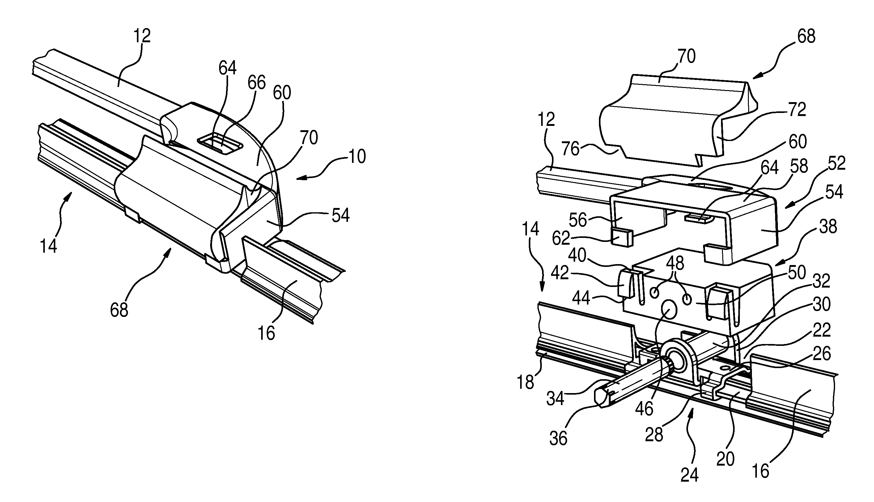
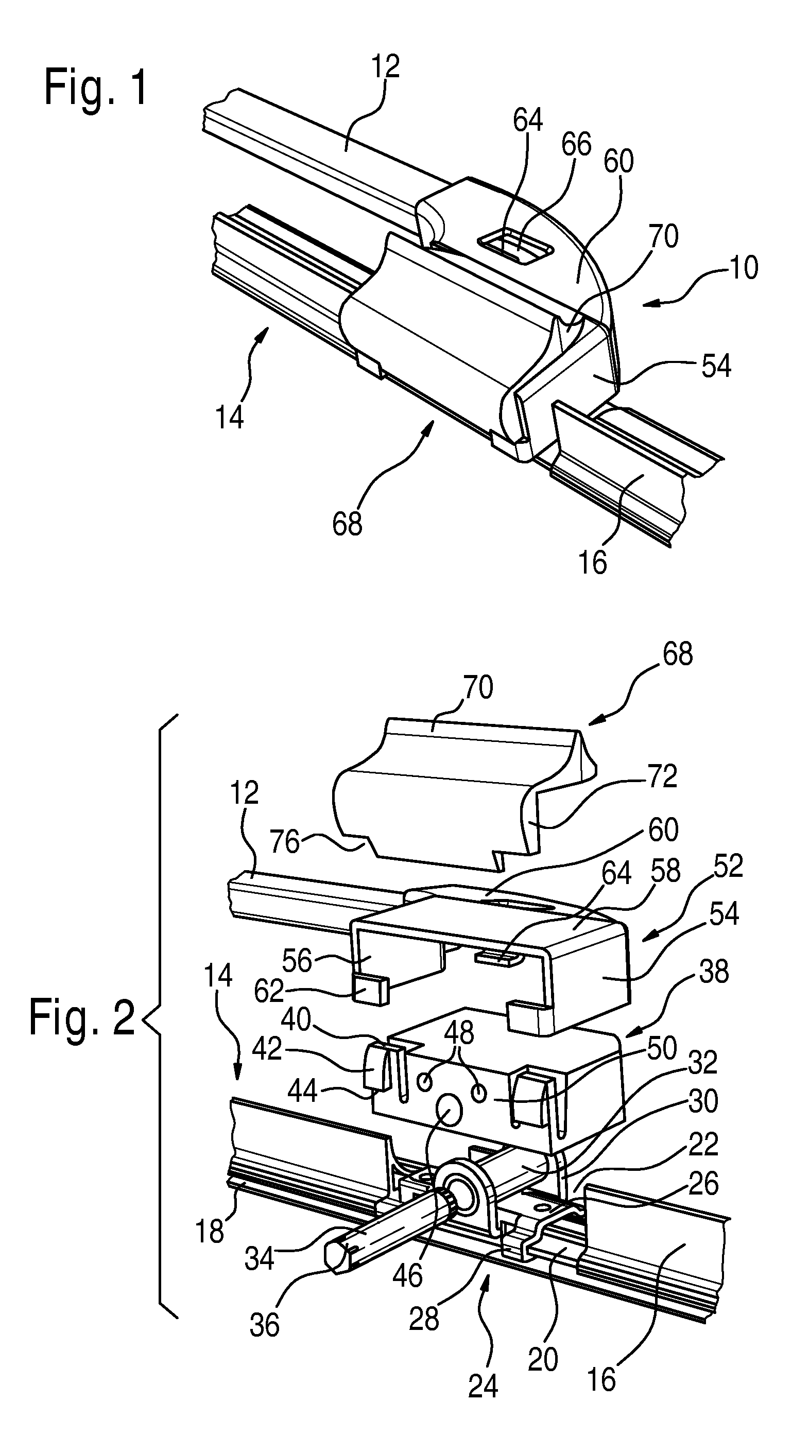
[0020]A wiper blade 14 is connected in a pivoted manner to a wiper arm 12 via a device 10. The wiper blade 14 includes a wiper strip 18 and a support element 20 in the form of two parallel resilient rails on which a spoiler 16 is fastened. A connecting piece 24 is firmly connected to the support element 20 in a window 22 of the spoiler 16. This can be accomplished by welding and / or claws 28.
[0021]The connecting piece 24 has a base plate on which the claws 28 are molded, and from which lateral cheeks 30 emanate, which are bent away from the support element 20 towards the base plate 26 by approx. 90°. The lateral cheeks 30 carry a bearing bush 32 in which a bearing pin 34 is pivoted. The ends of the bearing pin 34 project laterally from the bearing bush 32 and have form closure elements 36, with which the bearing pin 34 is inserted in a rotational secured manner in openings 46 of the adapter 38.
[0022]The adapter 38 has a rectangular outer contour. Two clip elements 40 in the form of s...
PUM
Abstract
The invention relates to a device (10) for the pivoting connection of a wiper blade (14) to a wiper arm (12) of a windscreen wiper, comprising a connector element (52, 84, 100) fixed to the wiper arm (12) and a connector element (24) fixed to a support element (20) on the wiper blade (14), which supports a bearing element (32), forming a pivoting bearing with a bearing element (34) on an adapter (38, 80) made from plastic. The adaptor (38, 80) is fixed in the profile of the connector element (52, 84, 100) open in the direction of the connector element (24) by clip elements (40, 78, 82) and retainer elements (62, 64, 86, 90, 104). According to the invention, the connector element (52, 84, 100) is an essentially rectangular hollow body, open on the side facing the connector element (24), with a fixing element (60) molded on a longitudinal side thereof which covers the longitudinal side and is fixed to the end of the wiper arm (12) and at least the front walls (54, 56) and a cover wall (58) of the connector element (52, 84, 100) are essentially sealed.
Description
BACKGROUND OF THE INVENTION[0001]The invention relates to a device for the articulated connection of a wiper blade to a wiper arm of a windshield wiper.[0002]This type of device is known from WO 02 / 40328 A1. It is comprised of a connecting piece in the form of a sheet metal claw, an adapter made of plastic and a connecting element that is firmly connected to the wiper arm. The connecting piece is fastened to a support element of the wiper blade in the form of two parallel resilient rails by means of claws and / or by welding. It has a U-shaped cross-sectional profile, whereby, starting from a base part adjacent to the support element, lateral walls are bent away from the support element by approx. 90°. Openings are provided in the side walls, into which a bearing pin is inserted in a rotatably secured manner. Pivoted on this with a hub is the adapter, which is guided laterally between the lateral walls of the connecting piece. The adapter has clipping means and retainer means, which a...
Claims
Application Information
Patent Timeline
Application Date:The date an application was filed.
Publication Date:The date a patent or application was officially published.
First Publication Date:The earliest publication date of a patent with the same application number.
Issue Date:Publication date of the patent grant document.
PCT Entry Date:The Entry date of PCT National Phase.
Estimated Expiry Date:The statutory expiry date of a patent right according to the Patent Law, and it is the longest term of protection that the patent right can achieve without the termination of the patent right due to other reasons(Term extension factor has been taken into account ).
Invalid Date:Actual expiry date is based on effective date or publication date of legal transaction data of invalid patent.