Filter band for an electrohydraulic valve

a filter band and electrohydraulic valve technology, applied in the direction of filtration separation, moving filter element filter, separation process, etc., can solve the problem of adding complexity to the valve assembly process

Active Publication Date: 2012-05-29
HUSCO AUTOMOTIVE HLDG
View PDF28 Cites 21 Cited by
  • Summary
  • Abstract
  • Description
  • Claims
  • Application Information

AI Technical Summary

Problems solved by technology

Although the ball bearing worked very well, it added complexity to the valve assembly process.

Method used


Image

  • Filter band for an electrohydraulic valve
  • Filter band for an electrohydraulic valve
  • Filter band for an electrohydraulic valve

Examples


Embodiment Construction

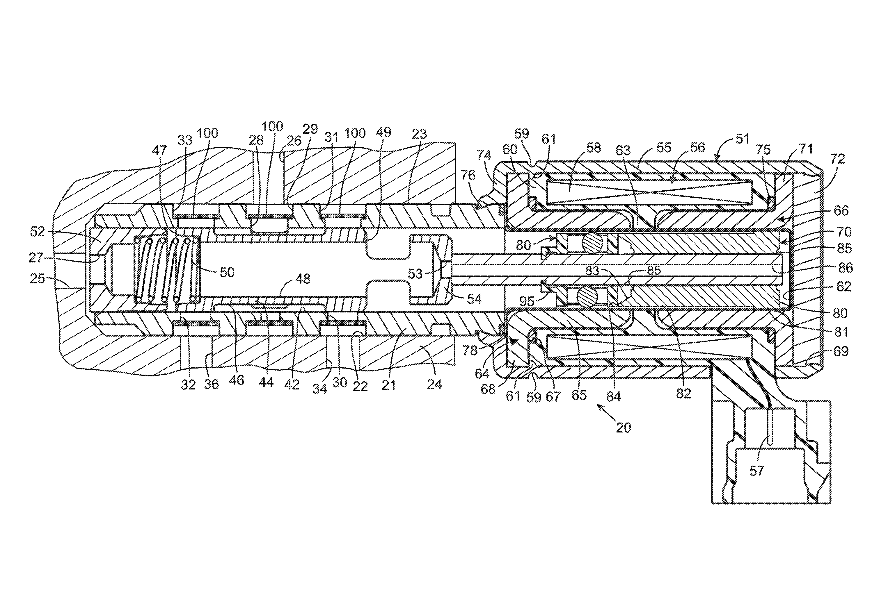
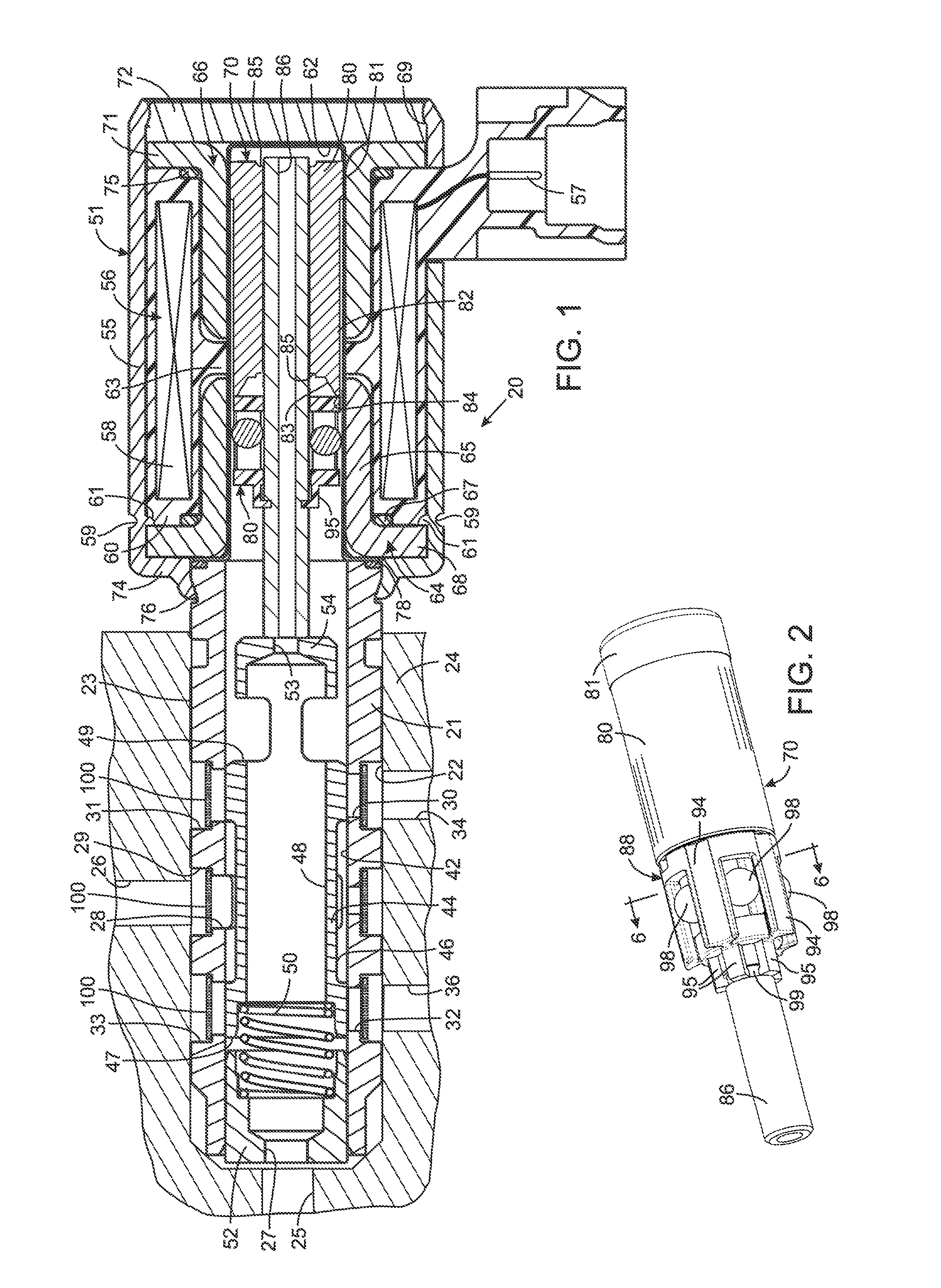
[0020]Referring to FIG. 1, an electrohydraulic control valve 20 has a tubular valve body 21 that during use is inserted into an aperture 22 in a manifold 24. The tubular valve body 21 has a longitudinal bore 42 into which a plurality of ports open. A supply passage 26 in the manifold 24 conveys pressurized fluid from a pump and a return passage 25 conveys fluid back to a tank of the hydraulic system in which the valve is incorporated. The supply passage 26 opens into an inlet port 28 of the control valve 20 and the return passage 25 at the end of the manifold aperture 22 communicates with an outlet port 27 of the valve. The inlet port 28 includes a first annular recesses 29 which is formed in an exterior curved surface 23 of the valve body 21. First and second workports 30 and 32 in the tubular valve body 21 communicate with passages 34 and 36 that lead to a hydraulic actuator being controlled. The first and second workports 30 and 32 include annular recesses 31 and 33 respectively ...


PUM

PropertyMeasurementUnit
non-magneticaaaaaaaaaa
operating speedsaaaaaaaaaa
resistanceaaaaaaaaaa

Abstract

An electrohydraulic valve has a valve body with a longitudinal bore and a cylindrical exterior surface. An annular recess extends around the cylindrical exterior surface and the first port extends from the recess to the bore. A filter is formed by a plate that has a plurality of perforations and which is wrapped around valve body in the recess. The plate has a first end section at which a first tab is created and a second end section overlapping the first end section with a slot through which the first tab extends to secure the first and second end sections together. A spool is slideable into different positions within the bore of the valve body to selectively connect and disconnect the first port and a second. An actuator is operably coupled to move the spool into different positions within the bore.

Description

CROSS-REFERENCE TO RELATED APPLICATIONS[0001]Not ApplicableSTATEMENT REGARDING FEDERALLY SPONSORED RESEARCH OR DEVELOPMENT[0002]Not ApplicableBACKGROUND OF THE INVENTION[0003]1. Field of the Invention[0004]The present invention relates to electrically operated spool valves that control flow of a fluid, and more particularly to electrical actuators, such as solenoids, for operating those valves.[0005]2. Description of the Related Art[0006]A wide variety of machines have moveable members that are operated by an hydraulic actuator. For example an internal combustion engine has a camshaft which is mechanically coupled to rotate with the crankshaft and which opens and closed cylinder intake and exhaust valves. Traditionally the camshaft timing was fixed at a setting that produced the best operation at all engine operating speeds. However, it has been recognized that engine performance can be improved if the valve timing varies as a function of engine speed, engine load, and other factors...

Claims


Application Information

Patent Timeline
Patent Type & Authority Patents(United States)
IPC IPC(8): E03B3/18F16K31/06E03B7/07
CPCF16K31/0613Y10T137/794Y10T137/8122
Inventor NORDSTROM, ROBERT SCOTTSTEPHENS, KIRT NATHANIELFLYNN, EDWARD ALOYSIUS
Owner HUSCO AUTOMOTIVE HLDG
Why Eureka
Try Eureka