Optical pickup unit and optical pickup device having same and information writing/reading device having same

a technology of optical pickup and information writing/reading, which is applied in the direction of digital signal error detection/correction, instruments, recording signal processing, etc., can solve the problems of inaccurate tracking signal and light quantity error, and achieve accurate and stably performing tracking control

Active Publication Date: 2012-05-29
SHARP KK
View PDF19 Cites 0 Cited by
  • Summary
  • Abstract
  • Description
  • Claims
  • Application Information

AI Technical Summary

Benefits of technology

[0016]In view of the above problems, the present invention is made, and it is an object of the present invention to provide an optical pickup device and an information writing / reading device each capable of accurately and stably performing tracking control, when writing information into a DVD±R by using plural light beams, without a need of increasing the number of auxiliary light-receiving sections.

Problems solved by technology

On this account, when the main beam reflected off the non-targeted layer enters each of the tracking-use sub light-receiving regions and the tracking-use main light-receiving region each being provided for finding out the tracking servo signal, an error occurs in a light quantity of the received light.
Consequently, an accurate tracking signal is not obtained.

Method used


Image

  • Optical pickup unit and optical pickup device having same and information writing/reading device having same
  • Optical pickup unit and optical pickup device having same and information writing/reading device having same
  • Optical pickup unit and optical pickup device having same and information writing/reading device having same

Examples


embodiment 1

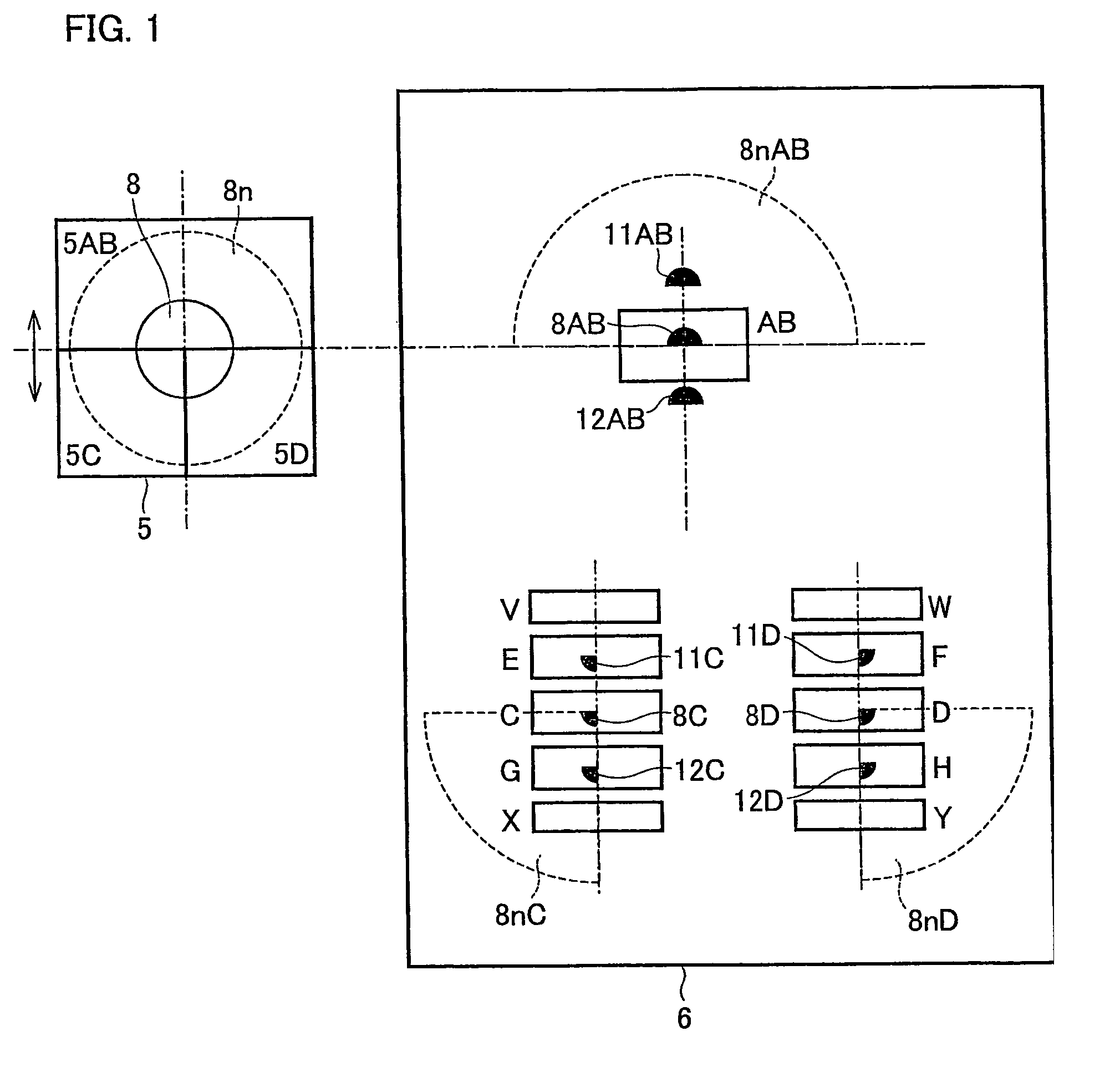
[0064]The following will describe Embodiment 1 of the present invention. An optical pickup device of the present embodiment is provided in an optical disc device (information writing / reading device) which optically reads and writes information from / onto a storage medium such as an optical disc. To write information onto a storage medium, the optical pickup device performs tracking control by means of a differential push-pull method (hereinafter, DPP) using three beams (one main beam and two sub beams).

[0065]In the following, plural writing-target layers of a storage medium are termed as follows: a writing-target layer to / from which information is not written / read by the optical pickup device is a non-targeted layer, whereas a writing-target layer to / from which information is written / read by the optical pickup device is a targeted layer. In other words, writing-target layers other than the target layer are non-targeted layers.

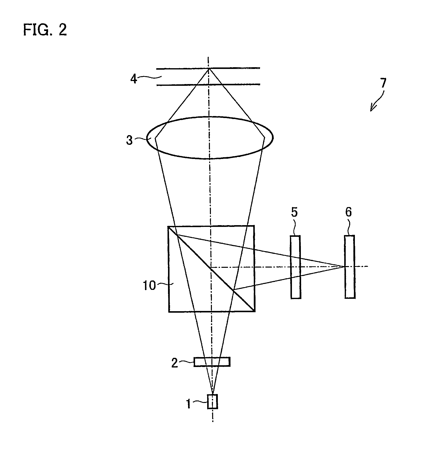
[0066]FIG. 2 is a side view which outlines an optical pick...

embodiment 2

[0115]The following will describe Embodiment 2 of the present invention. In the embodiment, members identical with those described in Embodiment 1 are given the same numbers, so that the descriptions are omitted for the sake of convenience.

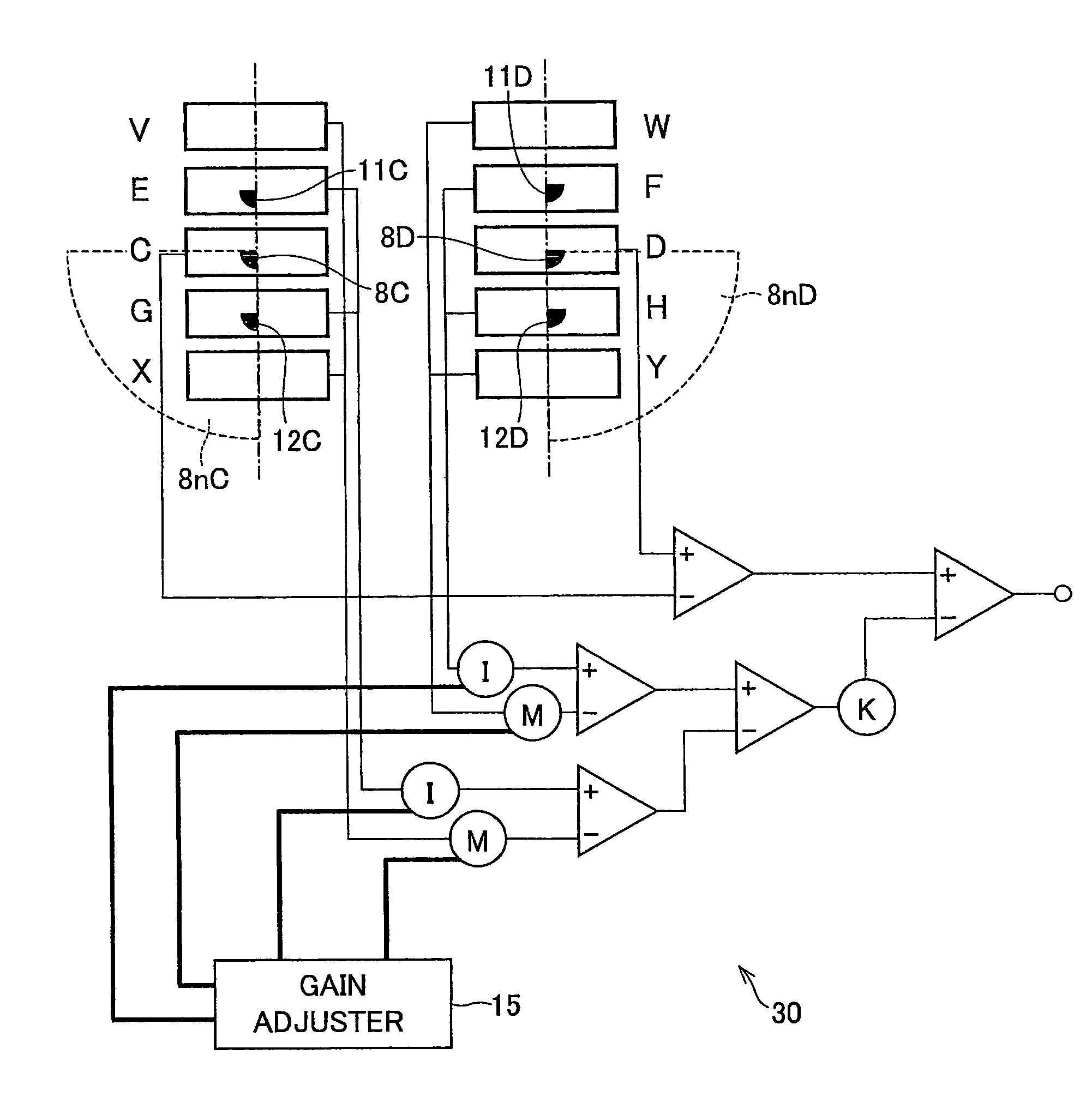
[0116]An optical pickup device 7 (see FIG. 2) of the present embodiment is arranged such that an arithmetic circuit for calculating a tracking servo signal based on the light intensity in each light-receiving region is connected to the light-receiving section 6, and the arithmetic circuit is provided with a gain adjuster which adds gain to an output signal generated based on the light intensity in each light-receiving region.

[0117]FIG. 5 shows a part of the light-receiving section 6 of the present embodiment and the arithmetic circuit 30 which is connected to the light-receiving regions of the light-receiving section 6. Since the light-receiving section 6 is identical with that of Embodiment 1 except the shape of an auxiliary light-receiving regio...

embodiment 3

[0143]The following will describe Embodiment 3 of the present invention. In the embodiment, members identical with those described in Embodiment 1 are given the same numbers, so that the descriptions are omitted for the sake of convenience.

[0144]An optical pickup device 7 (see FIG. 2) of the present embodiment is arranged in such a manner that the regions 5C and 5D of the hologram 5, by which regions light beams are split in order to obtain a tracking servo signal, do not include a region around the optical axis of the main beam. FIGS. 7 and 8 show the hologram 5 and the light-receiving section 6 of the optical pickup device of the present embodiment. As shown in these figures, the shapes of the regions 5AB, 5C, and 5D of the hologram 5 are different from those of the hologram 5 of Embodiment 1. Other than this, the present embodiment is identical with Embodiment 1.

[0145]FIG. 7 is a frontal view showing the spots of the light beams reflected off the targeted layer and the spots of t...


PUM

PropertyMeasurementUnit
wavelengthaaaaaaaaaa
radiusaaaaaaaaaa

Abstract

An optical pickup device includes: a splitting section for splitting a beam; a light-receiving section for receiving the split beams. The light-receiving section includes: a tracking-use main light-receiving region and tracking-use sub light-receiving regions, and auxiliary light-receiving regions. Each of the auxiliary light-receiving regions receives only a light beam reflected off a recording layer other than a recording layer subjected to an information writing / reading process. A light-receiving area of each of the auxiliary light-receiving area is smaller than a light-receiving area of each tracking-use light-receiving region. Further, an optical pickup device includes: a splitting section for splitting a beam; and a light-receiving section for receiving the split beams. The light-receiving section includes a sub light-receiving regions for receiving tracking-use sub beams. The tracking-use sub beams are arranged so as not to allow entering of a focusing-use main beam reflected off a non-targeted recording layer.

Description

TECHNICAL FIELD[0001]The present invention relates to an optical disc device (information writing / reading device) capable of writing or reading information into / from a storage medium such as an optical disc, and relates to an optical pickup device and an optical pickup unit used in the optical disc device.BACKGROUND ART[0002]To record high-resolution moving pictures on a single optical disc (storage medium), the optical disc needs to have an increased capacity for recording. An approach for achieving this is to provide plural writing-target layers (information writing layers) to an optical disc. Read-only single-sided double layer discs such as DVD-ROM, DVD-Video have been widely marketed, and are commercially available. Meanwhile, a standard for information-writable single-sided double layer optical discs has been already announced, and commercialization of such optical discs is just a matter of time.[0003]Here, an optical-disc having plural writing-target layers has a problem of u...

Claims


Application Information

Patent Timeline
Patent Type & Authority Patents(United States)
IPC IPC(8): G11B7/00G11B7/135G11B7/09G11B7/13
CPCG11B7/0903G11B7/131G11B7/1353G11B7/0943G11B2007/0013
Inventor MIYAZAKI, OSAMUSAKAI, KEIJIWATANABE, YUKIO
Owner SHARP KK
Why Eureka
Try Eureka