Slip control device

a control device and a technology for detecting and controlling the inclination of the vehicle, which are applied in the direction of electric devices, braking systems, tractors, etc., can solve the problems of low communication speed of the communication area network of the control area generally employed in the automobile, the delay of the motor torque command, and the inability to perform control design relatively easily, so as to achieve stably and accurately perform the inclination control

Active Publication Date: 2020-05-26
NTN CORP
View PDF19 Cites 1 Cited by
  • Summary
  • Abstract
  • Description
  • Claims
  • Application Information

AI Technical Summary

Benefits of technology

[0011]The present invention has been made in order to solve the above-described problems, and an object of the present invention is to provide a slip control device that inhibits a vehicle tire slip in an electric automobile in which each wheel serving as a drive wheel is driven by an electric motor, and that, even in a case where there is a relatively long dead time from output of a torque command by a vehicle controller to input of a wheel rotation speed that is fed back to the vehicle controller, can stably and accurately perform slip control, and enables control designing to be relatively easily performed.
[0021]With this configuration as a basis, the dead time compensator 17 using the Smith method is provided, and, as a torque to be inputted to the dead time compensator 17, the P compensation (proportional compensation) excluding the I compensation (integral compensation) from the PI compensation, or a sum KPD of the P compensation and the D compensation (differential compensation) excluding the I compensation from the PID compensation, is used. Accordingly, a steady-state deviation due to the dead time compensation by the I compensation (integral compensation) or a torque command value does not occur, whereby the accuracy of control is improved. Therefore, a slip control device can be provided in which, even in a case where there is a relatively long dead time from output of the torque command by the vehicle controller to input of the wheel rotation speed that is fed back to the vehicle controller, slip control can be stably and accurately performed, and control designing can be relatively easily performed.
[0023]In the slip control device 1 according to the present invention, an I compensator 23 included in the PI / PID controller 13 may limit a magnitude of the I compensation based on an absolute value (AB=|Tin|) of the torque command input value Tin received from the higher-order controller 3. That is, the magnitude of the I compensation, i.e., the integral compensation in the PID calculation or the PI calculation is limited based on the magnitude of the torque command input value Tin for driving or braking calculated from, for example, a stroke amount of an accelerator pedal 8 or a pedaling force on a brake pedal 9 by the higher-order controller 3 and that is received by the slip control device 1. Accordingly, responsiveness to changes in a target value and a disturbance (a torque command value Tin received from the higher-order controller 3, and a reaction force, from a road surface, that acts on the tire) can be improved.

Problems solved by technology

In the technology disclosed in Patent Document 1, in a case where the speed of communication between the vehicle controller and the motor controller is low when the motor torque command value calculated by the vehicle controller is transmitted from the vehicle controller to the motor controller, there is a possibility that delay in a motor torque command occurs owing to the communication, and motor control to be performed by the motor controller is also delayed.
For example, the communication speed of communication by a CAN (control area network) generally employed in an automobile is low, since such communication is time-multiplexed serial communication in which communication between components is sequentially performed on the same wiring.
In an actual control device, a delay in calculation of an inverter in a motor controller, a delay in detection by a wheel speed sensor, and other delays occur besides the above-described delay due to communication speed, and, besides a delay caused by inertia of a wheel, various delays occur from output of a torque command by the vehicle controller to input of a wheel rotation speed that is fed back to the vehicle controller.
In a case where the dead time is included, the effect of control input does not immediately appear as an output, and the output is not immediately fed back to the controller, and thus, when the vehicle controller is to perform slip control on the basis of the value of the wheel rotation speed, the control is likely to become more difficult with only PID compensation as the dead time becomes longer.
With this method, although satisfactory response to a target input can be obtained, response to a disturbance may not always be satisfactory.
In applying the Smith method to slip control for a wheel, change in a command torque due to, for example, an acceleration operation by a driver and a fluctuation in a reaction force, from a road surface, that acts on a tire act as disturbances, and thus, there is a possibility that the controllability is deteriorated.
However, by the introduction of the additional compensator, man-hours are required to perform control designing.

Method used


Image

  • Slip control device
  • Slip control device
  • Slip control device

Examples


Embodiment Construction

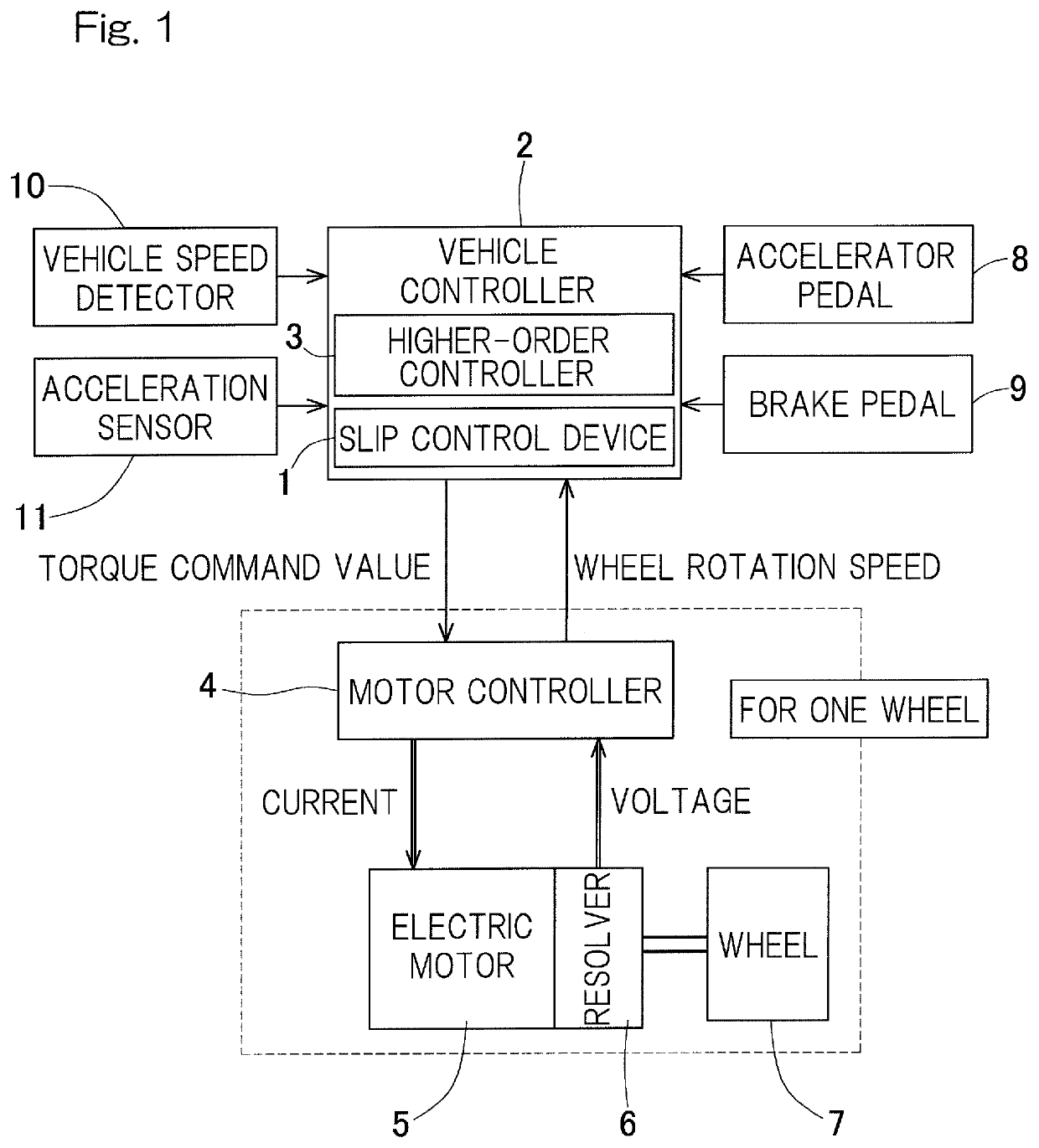
[0031]One embodiment of the present invention will be described with reference to the drawings. FIG. 1 is a system configuration diagram indicating a control system, of a vehicle such as an electric automobile, which includes a slip control device 1. The slip control device 1 is provided in a vehicle controller 2. In FIG. 1, a motor controller 4, an electric motor 5, a resolver 6, and a wheel 7 are shown for one of wheels 7, but these components may be provided for each of the wheels 7 serving as drive wheels. For example, the number of each of these components provided in a four-wheel drive vehicle is four. The number of each of these components provided in a two-wheel drive vehicle is two.

[0032]The electric motor 5 is a three-phase AC motor such as a synchronous magnet-embedded type or interior permanent magnet motor. The electric motor 5 may be an induction motor or may be a DC motor. The electric motor 5 may be a motor included in an in-wheel motor drive device, or may be an on-...


PUM


Abstract

A PI / PID controller that generates a torque compensation value KPID through PI control or PID control, from a deviation between an allowable rotation speed and a rotation speed of a wheel; an adder that adds the torque compensation value to a torque command input value received from a higher-order controller, thereby obtaining a torque command output value; and a dead time compensator that has a control target model including a dead time and that applies a dead time compensation in generation of the torque compensation value by the Smith method. An input to the dead time compensator is an output of a P compensation or a PD compensation excluding an I compensation from a PI compensation or a PID compensation.

Description

CROSS REFERENCE TO THE RELATED APPLICATION[0001]This application is a continuation application, under 35 U.S.C. § 111(a), of international application No. PCT / JP2016 / 081855, filed Oct. 27, 2016, which is based on and claims Convention priority to Japanese patent application No. 2015-215393, filed Nov. 2, 2015, the entire disclosure of which is herein incorporated by reference as a part of this application.BACKGROUND OF THE INVENTIONField of the Invention[0002]The present invention relates to a slip control device for inhibiting a vehicle tire slip, and particularly relates to a slip control device for, for example, an electric automobile in which left and right wheels are independently driven by drive sources such as electric motors.Description of Related Art[0003]Conventionally, there are known slip control devices that each prevent a wheel from spinning or being locked at the time of acceleration of the vehicle body or at the time of deceleration of the vehicle body. In recent yea...

Claims


Application Information

Patent Timeline
Patent Type & Authority Patents(United States)
IPC IPC(8): B60K1/02B60L3/10B60L15/20B60T8/00B60W30/18B60K28/16B60W50/00
CPCB60L15/20B60L3/102B60K28/16B60T8/00B60W30/18172B60K1/02B60W2520/10B60W2050/0054B60L2220/46B60W2520/28B60W2720/28B60L2220/44B60L2240/461B60L2240/24B60W2050/0011B60W2540/18B60L2240/465B60L2260/42B60L2250/26Y02T10/7275B60L2240/463Y02T10/72
Inventor SUGAI, TOMOHIRO
Owner NTN CORP
Why Eureka
Try Eureka