Process cartridge with portions to be supported and regulated during insertion of the cartridge into an electrophotographic image forming apparatus

a technology of electrophotographic image and process cartridge, which is applied in the direction of electrographic process apparatus, optics, instruments, etc., can solve the problems of complex structure of process cartridges and rising costs, and achieve the effects of improving the mounting operation, stably mounting the process cartridge, and simplifying the structure of mounting

Active Publication Date: 2012-08-21
CANON KK
View PDF50 Cites 39 Cited by
  • Summary
  • Abstract
  • Description
  • Claims
  • Application Information

AI Technical Summary

Benefits of technology

[0012]It is another object of the present invention to provide a process cartridge and an electrophotographic image forming apparatus in which the mounting operativity in the mounting, to the apparatus main assembly, of the process cartridge is improved.
[0027]According to the present invention, by accomplishing the structure of raising whole process cartridges, the contacted state between the photosensitive drum and the transfer belt can stably be maintained.

Problems solved by technology

Then, a cartridge structure is complicated and the cost rising results.

Method used


Image

  • Process cartridge with portions to be supported and regulated during insertion of the cartridge into an electrophotographic image forming apparatus
  • Process cartridge with portions to be supported and regulated during insertion of the cartridge into an electrophotographic image forming apparatus
  • Process cartridge with portions to be supported and regulated during insertion of the cartridge into an electrophotographic image forming apparatus

Examples


embodiment 1

[Embodiment 1]

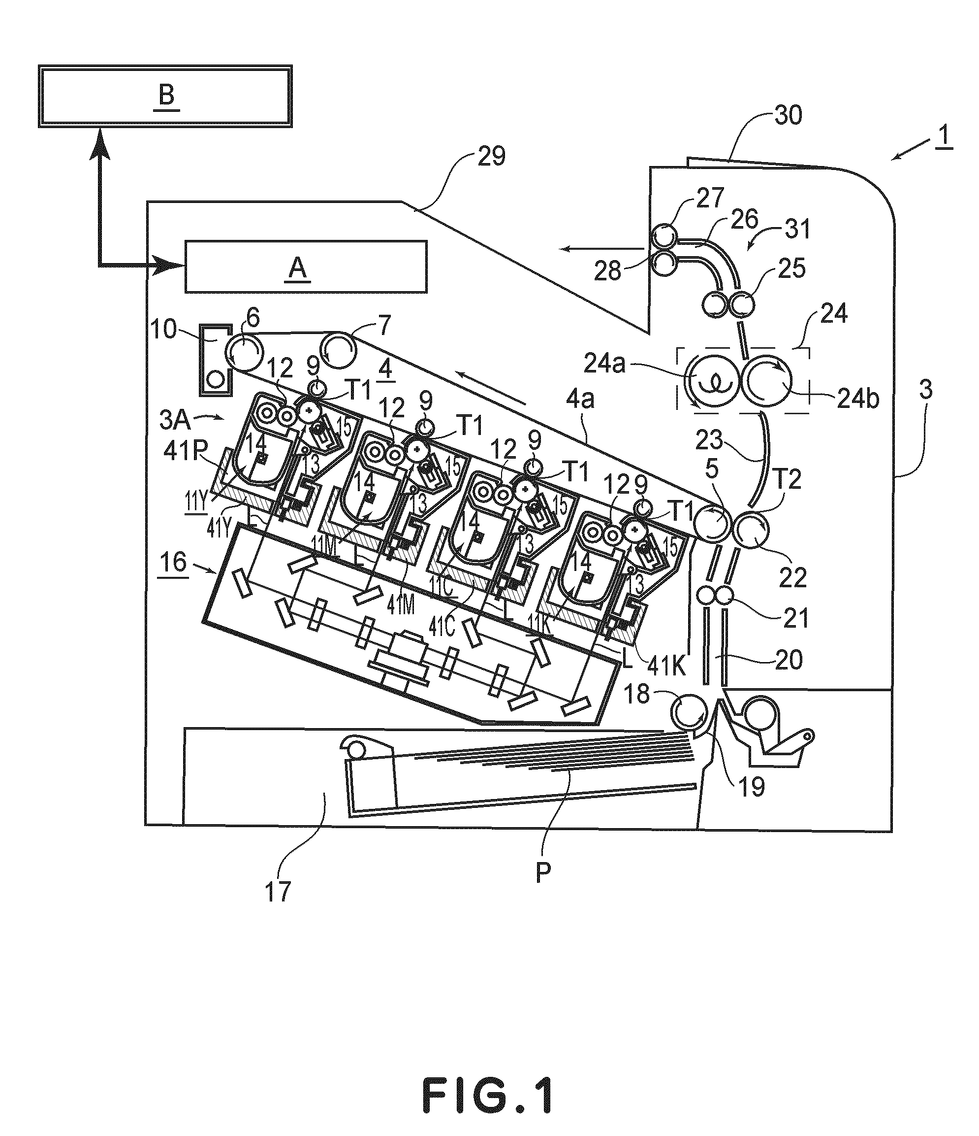
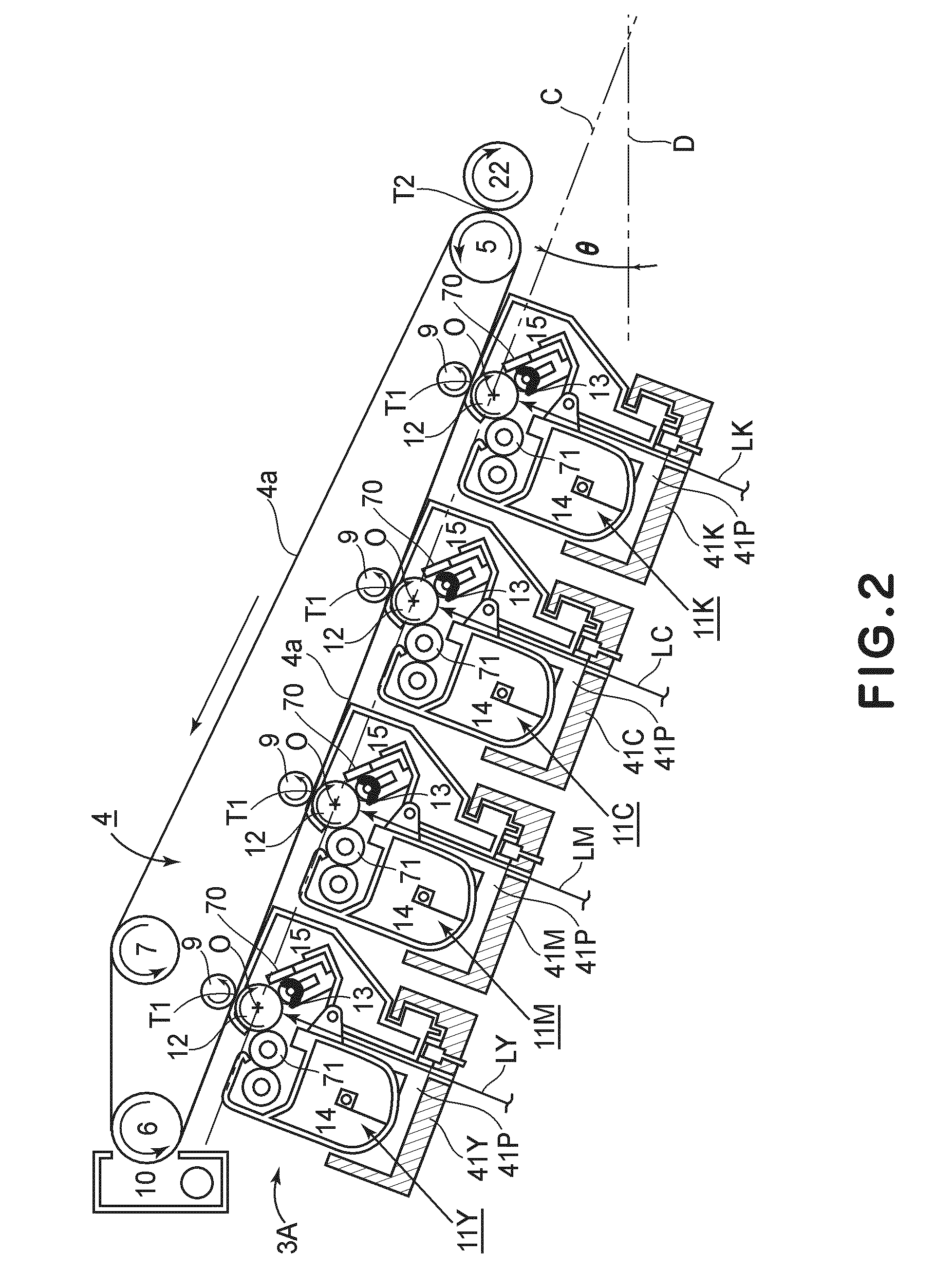
[0041]FIG. 1 is a schematic vertical sectional view of the image forming apparatus 1 in this embodiment, at a plane parallel to the front panel of the apparatus, when the apparatus is in operation. FIG. 2 is an enlarged schematic sectional view of the portion of the image forming apparatus 1 in this embodiment, which is pertinent to the description of the present invention. FIG. 3 is an external perspective view of the image forming apparatus 1 when the external door 2 (front door) of the apparatus 1 is open. FIG. 4 is an external perspective view of the image forming apparatus 1, the cartridge 11Y of which is partway out of the image forming apparatus 1.

[0042]In the following description of the preferred embodiments of the present invention, the front side or operator side (user side) means the side on which the external door 2 is present. In terms of the direction in which the cartridge 11 is mounted into the apparatus 1, the front side is the upstream side. In terms...

embodiment 2

[Embodiment 2]

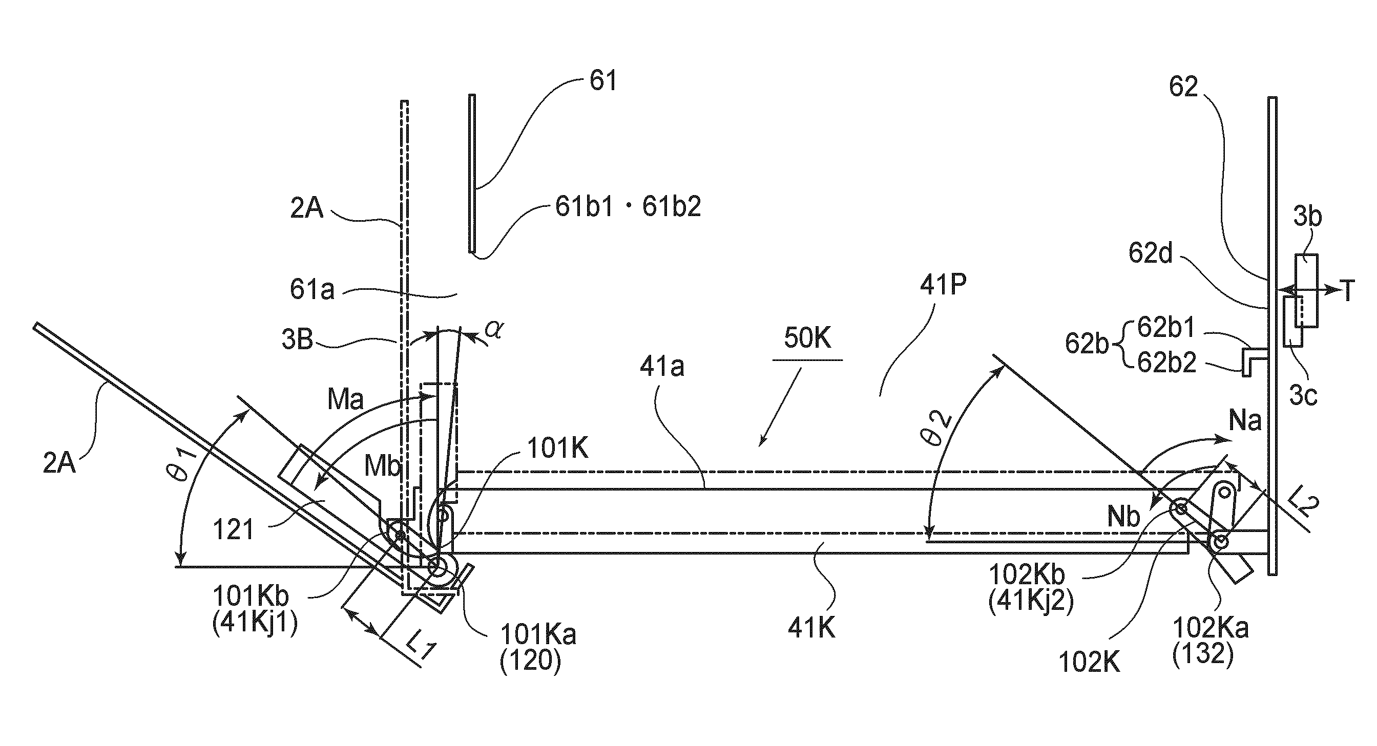
[0127]Referring to FIG. 12, in this embodiment, the frame 38 of the development unit 14 is provided with a support portion 38c. Further, the supporting member 41, with which the apparatus main assembly 3 is provided, roughly matches the support portion 38c of the development unit 14 in shape and size. Otherwise, the image forming apparatus in this embodiment is roughly the same in structure as that in the first embodiment.

[0128]As the cartridge 11 is inserted into the apparatus main assembly 3 in such a manner that the lengthwise direction of the cartridge 11 becomes parallel to the front-to-rear direction of the apparatus main assembly 3, the cartridge 11 is supported by the supporting member 41, by the support portion 38c of the cartridge 11. As the external door 2 is closed, the supporting member 41 in this embodiment also moves from its second position to the first position in the same manner as that in the first embodiment. That is, while the cartridge 11 is moved...


PUM


Abstract

A process cartridge detachably mountable to a main assembly of an electrophotographic image forming apparatus, wherein the apparatus includes a supporting member, a movable member for moving the supporting member in a horizontal direction and upward and downward directions, an operating member for moving the movable member, and a regulating portion, the process cartridge includes an electrophotographic photosensitive drum; process means actable on the drum; a portion to be supported for being supported by the supporting member when the process cartridge is mounted to the main assembly of the apparatus; and a portion-to-be-regulated for being regulated by being contacted by the regulating portion to regulate movement of the process cartridge in the horizontal direction, when the supporting member is moved, by movement of the movable member by operation of the operating member and in the horizontal direction and the upward direction while supporting the process cartridge, wherein when the supporting member is moved in the horizontal direction and upward direction while supporting the process cartridge, the portion-to-be-supported slides on the supporting member, and the portion-to-be-regulated slides on the regulating portion.

Description

FIELD OF THE INVENTION AND RELATED ART[0001]The present invention relates to a process cartridge detachably mountable to an apparatus main assembly of an electrophotographic image forming apparatus, and the electrophotographic image forming apparatus using the same.[0002]Here, the electrophotographic image forming apparatus (image forming apparatus) is the device which forms the image on a recording material P using an electrophotographic image forming process. For example, it includes an electrophotographic copying machine, an electrophotographic printer (an LED printer, a laser beam printer, and so on), an electrophotographic facsimile device, an electrophotographic word processor, and so on.[0003]Recording material P is the material on which the image is formed, and it includes a paper sheet, for example, a recording sheet, an OHP sheet, and a label.[0004]In addition, the process cartridge is a cartridge which comprises integrally a photosensitive drum (photosensitive drum) and a...

Claims


Application Information

Patent Timeline
Patent Type & Authority Patents(United States)
IPC IPC(8): G03G21/18
CPCG03G21/185G03G2215/0132G03G2215/0148G03G2221/169G03G2221/1869
Inventor HORIKAWA, TADASHIKAWAI, TACHIOTAKARADA, HIROSHINAKANISHI, TAKASHI
Owner CANON KK
Why Eureka
Try Eureka