Coil component

a technology of coils and components, applied in the direction of coils, printed circuit non-printed electric components association, transformer/inductance details, etc., can solve the problems of easy cutting of the connection between the terminals poor height accuracy, and high load on the terminal, so as to improve the reliability of connection between the terminal and the printed circuit board, the effect of reducing the load on the terminal and good height accuracy

Active Publication Date: 2010-06-24
TDK CORPARATION
View PDF4 Cites 42 Cited by
  • Summary
  • Abstract
  • Description
  • Claims
  • Application Information

AI Technical Summary

Benefits of technology

[0013]According to the embodiments described above, the terminal board is on the first flange which is on upper side compared with the second flange, the terminal sticking out from the terminal board extends downward to be inserted into the through-hole of the printed circuit board, and the downside surface of the second flange partly touches an upside surface of the printed circuit board, therefore weight o

Problems solved by technology

In the case where the terminals are partially springy like the transformer in the first patent document, even if the terminal and the board steadily touch each other, there is a problem that a connection between the terminals and the board is easy to be cut off because force of vibration or shock after soldering is applied to the soldering part connecting the terminals and the board.
Another problem is that whole weight of the transf

Method used


Image

  • Coil component
  • Coil component
  • Coil component

Examples


Embodiment Construction

[0023]The invention will now be described based on the following embodiments which do not intend to limit the scope of the present invention but exemplify the invention. All of the features and the combinations thereof described in the embodiments are not necessarily essential to the invention.

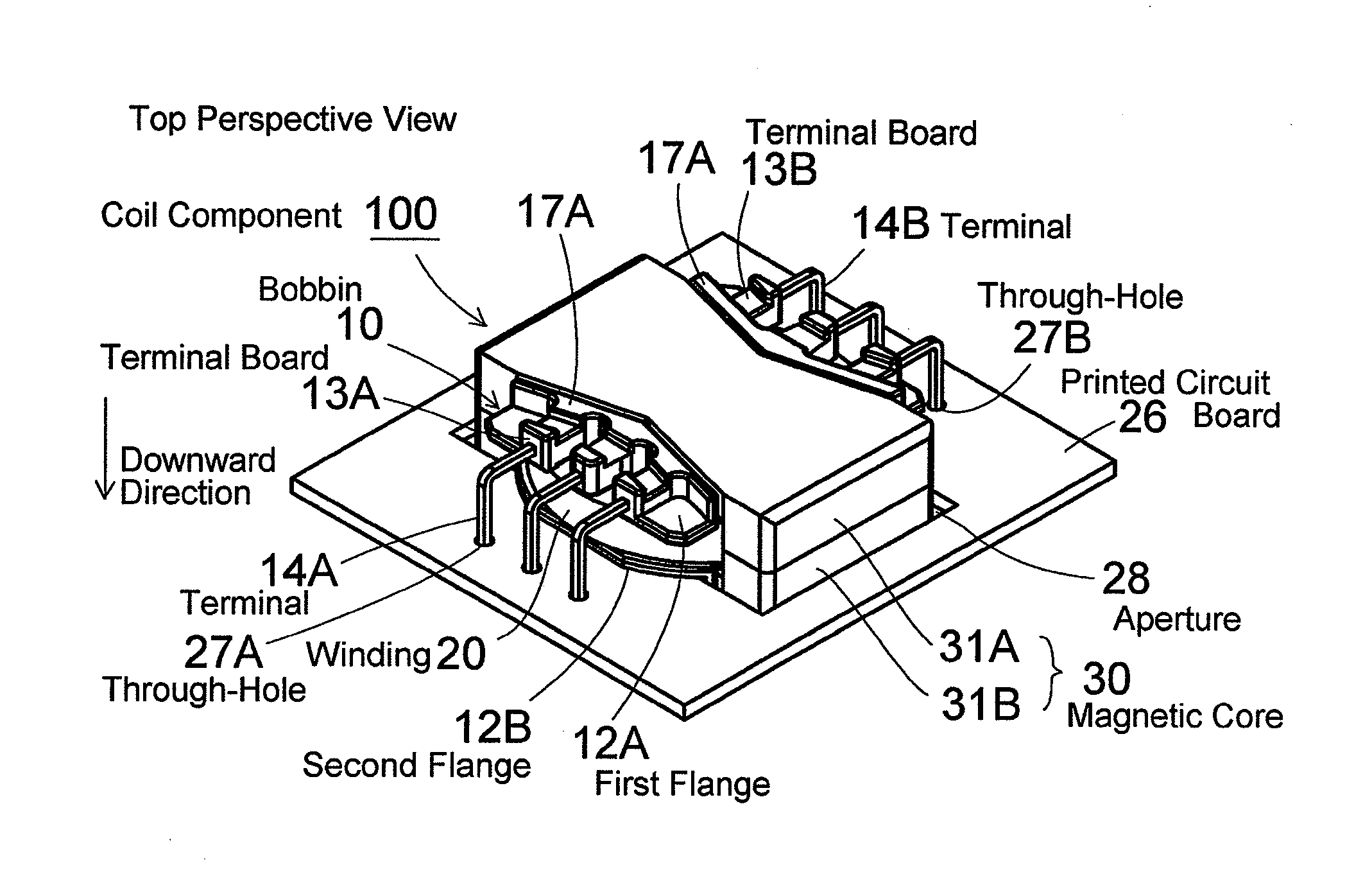
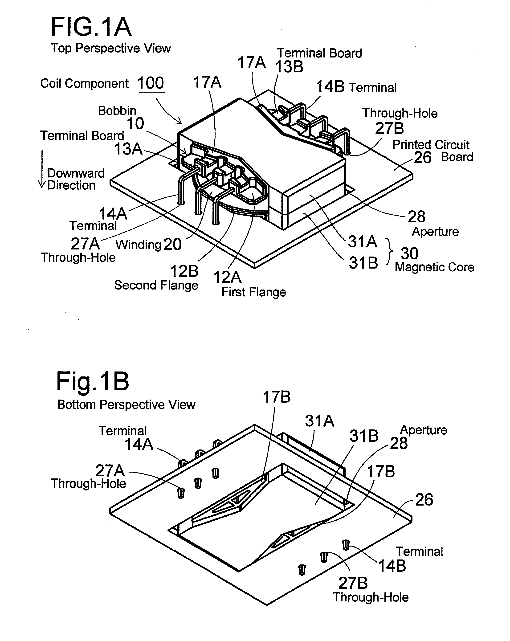
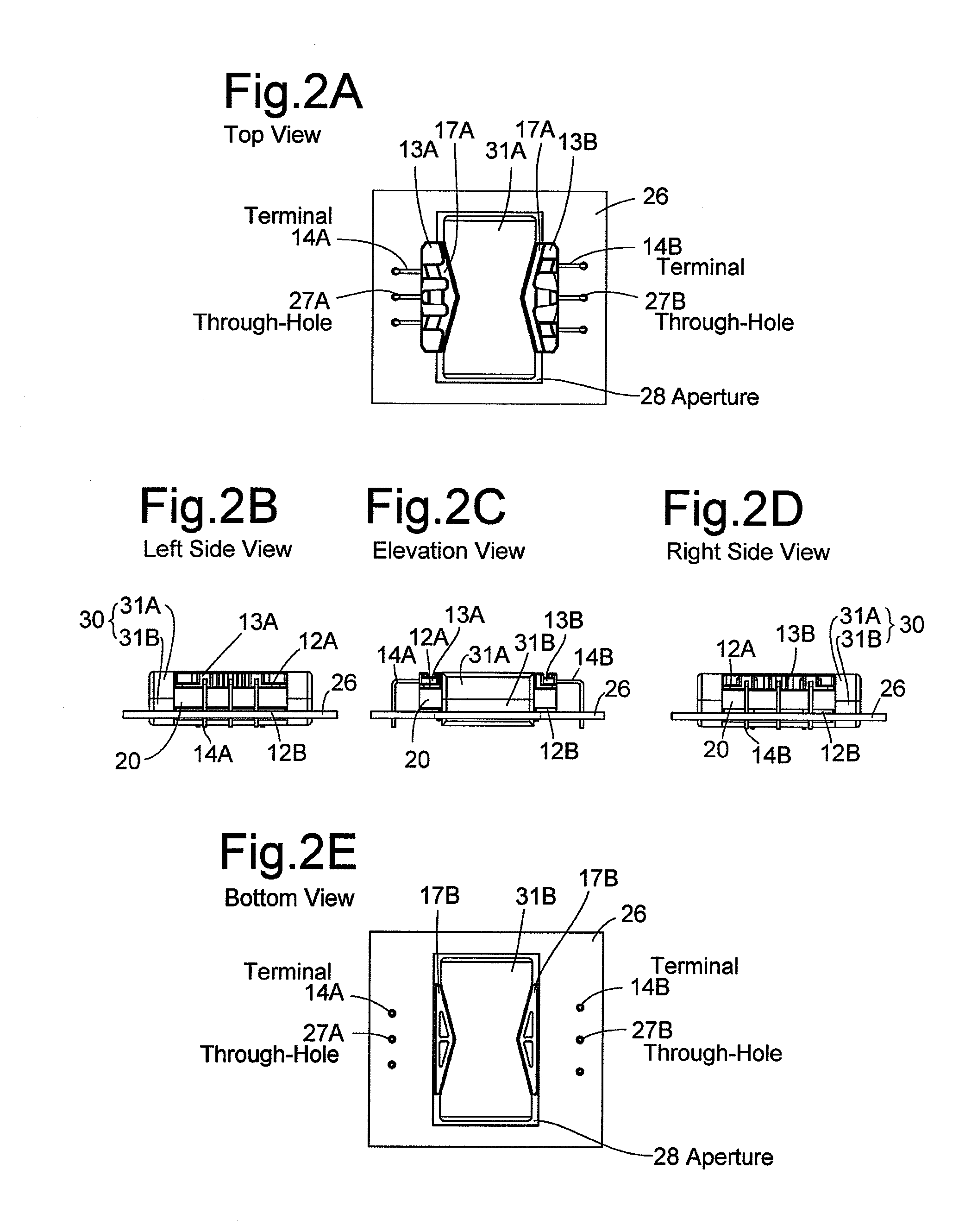
[0024]FIG. 1A is a top perspective view of a coil component 100 (already mounted on a printed circuit board 26) according to an embodiment of the present invention, and FIG. 1B is a bottom perspective view thereof. FIG. 2A is a top view of the coil component 100 (already mounted on the printed circuit board 26), FIG. 2B is a left side view thereof, FIG. 2C is an elevation view thereof, FIG. 2D is a right side view thereof, and FIG. 2E is a bottom view thereof. FIG. 3A is a top perspective view of the coil component 100 (not yet mounted on the printed circuit board 26), and FIG. 3B is a bottom perspective view thereof. FIG. 4A is a top view of the coil component 100 (not yet mounted on the prin...


PUM


Abstract

A coil component that can be mounted on a printed circuit board, with a part in an aperture of the printed circuit board. The coil component includes a first flange on an upper side and a second flange. Terminal boards are on respective opposite sides of the first flange. Terminals respectively project in a direction perpendicular to an axial direction of a winding drum, from the terminal boards and bend and are inserted into through-holes of the printed circuit board. First and second touching surfaces, which are parts of a downside surface of the second flange, touch an upside surface of the printed circuit board.

Description

BACKGROUND OF THE INVENTION[0001]1. Field of the Invention[0002]The present invention relates to a coil component used as a choke coil or a transformer (e.g., a resonance transformer used in a resonance type power supply), etc.[0003]2. Description of the Related Art[0004]From the point of view of lowering height, there are some cases where a choke coil or a transformer in a power supply of flat panel televisions etc is mounted on a printed circuit board, with a part thereof in an aperture of the printed circuit board. The first patent document, Japanese Patent Application Laid-Open No. 2001-57310 relates to a transformer which is simply mounted on the board or a part of which is in an aperture of the board. The first patent document says that the transformer has no conduction fault, because a part of each terminal is like spring or because the terminals are partially thin to be springy so that the terminal and the board steadily touch each other when the transformer is mounted on th...

Claims


Application Information

Patent Timeline
IPC IPC(8): H01F27/06
CPCH01F27/306H01F27/325H01F2005/043H05K1/18H01F2027/2819H01F2027/297H01F2027/065
Inventor YAMAGUCHI, KENICHIKITAJIMA, NOBUO
Owner TDK CORPARATION
Why Eureka
Try Eureka