Display device and timepiece

a technology of display device and timepiece, which is applied in the direction of clock apparatus, timer, instruments, etc., can solve the problems of extremely narrow area outside the image display area, i.e., the frame portion, and achieve the effect of narrowing the frame area, reducing the space needed for installation, and improving the utility of the position of the pin connected

Active Publication Date: 2012-06-05
138 EAST LCD ADVANCEMENTS LTD
View PDF28 Cites 20 Cited by
  • Summary
  • Abstract
  • Description
  • Claims
  • Application Information

AI Technical Summary

Benefits of technology

[0014]A first aspect of the invention is a display device that enables narrowing the frame area around the image display area while also reducing the space needed for installation in a device or product, improves the utility of the positions of the pins connected to the device-side circuit board, and affords easier connection and disconnection of the display device to the device-side circuit board. Another aspect of the invention is a timepiece having this display device.

Problems solved by technology

As a result, the area outside the image display area, that is, the frame portion, can be extremely narrow.

Method used


Image

  • Display device and timepiece
  • Display device and timepiece
  • Display device and timepiece

Examples


embodiment 2

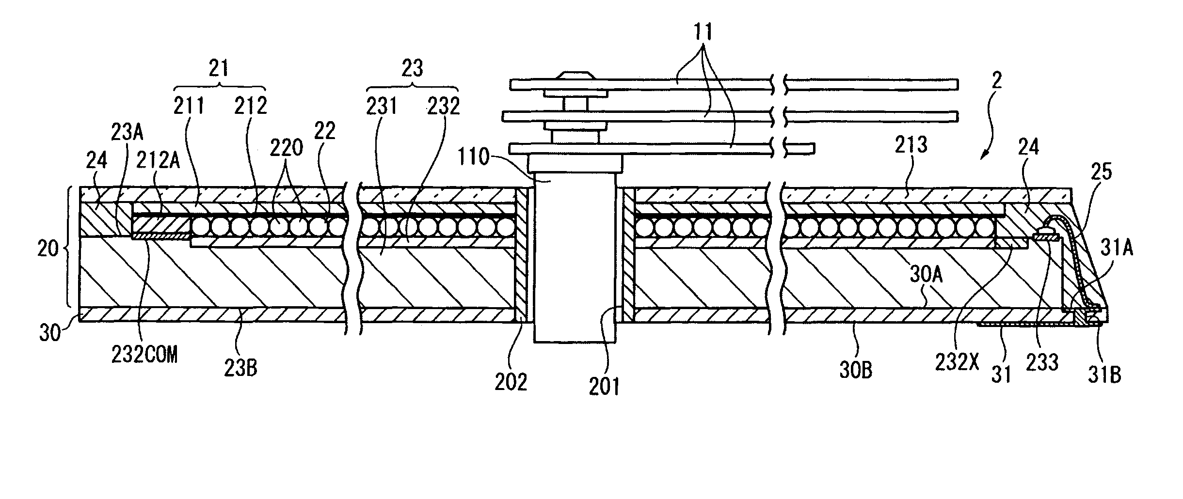
[0095]A second embodiment of the invention is described next with reference to FIG. 7. FIG. 7 is a schematic section view of the display device 5 according to this embodiment of the invention. A plurality of electronic components 61 to 64 are mounted on the back side 30B of the wiring board 50 of the display device 5. These electronic components include a drive circuit IC 61 for the display panel 20, a temperature sensor 62, and a photodetector 63 such as a photodiode rendering a position detection sensor for sensing the rotational position of the wheels to which the hands 11 are attached

[0096]A plurality of pins 610 on the back side 30B of the wiring board 50 are electrically connected through vias to the patterns 31A on the front side 30A of the wiring board 50. Connection pins 31 that are conductive to selected input / output pins 233 through the patterns 31A are formed on the back side 30B of the wiring board 50.

[0097]The temperature sensor 62 is disposed at a position correspondi...


PUM

PropertyMeasurementUnit
areaaaaaaaaaaa
dielectric elasticaaaaaaaaaa
adhesionaaaaaaaaaa

Abstract

A display device that has a display panel having a front substrate, an image forming unit, and a back substrate rendered together in layers, and a wiring board layered on the back surface of the back substrate. A plurality of input / output pins are formed on the front surface of the back substrate, and a plurality of connection pins that are electrically connected to the input / output pins by respective conductor members are formed on the back surface of the wiring board.

Description

CROSS-REFERENCE TO RELATED APPLICATIONS[0001]Japanese Patent application No. 2007-290684 is hereby incorporated by reference in its entirety.BACKGROUND[0002]1. Field of Invention[0003]The present invention relates to a display device and a timepiece.[0004]2. Description of Related Art[0005]A display device according to the related art as depicted in Japanese Unexamined Patent Appl. Pub. JP-A-2007-133182 bonds the terminal portions of a wiring board overlapping the conductor portions of the display panel disposed outside the display area. These conductor portions and wiring board each have a plurality of pins, and adhesion by an anistropic conductive film is used to connect the pins of the conductor portion with the pins of the wiring board.[0006]The display panel has a top substrate, a transparent electrode formed on the top substrate, a bottom substrate on which the pixel electrodes are formed, and an image forming layer including liquid crystals or electrophoretic particles render...

Claims


Application Information

Patent Timeline
Patent Type & Authority Patents(United States)
IPC IPC(8): G02F1/1345G04C19/00G02F1/167
CPCG02F1/13452G04G9/0082G02F1/1339H01R12/7076G02F1/167
Inventor SEKI, SHIGEAKIOKUHARA, KENICHI
Owner 138 EAST LCD ADVANCEMENTS LTD
Why Eureka
Try Eureka