Display device and manufacturing method thereof

a technology of display device and manufacturing method, which is applied in the direction of lighting and heating apparatus, planar/plate-like light guides, instruments, etc., can solve the problems of increased manufacturing process, complicated structure, and large frame area of display device, and achieve the effect of increasing the manufacturing process

Inactive Publication Date: 2007-09-13
MITSUBISHI ELECTRIC CORP
View PDF3 Cites 12 Cited by
  • Summary
  • Abstract
  • Description
  • Claims
  • Application Information

AI Technical Summary

Benefits of technology

[0011]An object of the invention is to provide a display device using a light source that can have a narrow frame area and also simultaneously regulate the positions of a display panel, a middle frame, an optical sheet, a light guide plate and a reflective sheet without increasing a manufacturing process or providing a process of reversing the display device in assembly work.

Problems solved by technology

This complicates the structure and results in a larger frame area of a display device.
A process is required to reverse a display device (reversing the front / rear surface of a display device) in assembly, which has raised a problem of an additional manufacturing process.
This leads to a complicated structure and adds to the thickness of a display unit.
However, there is no disclosure or teaching regarding the position regulation of a display panel.
Another problem is that a position regulating structure of an optical sheet or a reflective sheet can be as thick as that of the optical or reflective sheet.
This results in a lower position regulating capability and involves difficulty in the assembly work and displacement of the optical or reflective sheet caused by vibration or impact even after a display device is assembled.

Method used


Image

  • Display device and manufacturing method thereof
  • Display device and manufacturing method thereof
  • Display device and manufacturing method thereof

Examples


Embodiment Construction

[0016]An embodiment of the invention will be described below. The description is meant to explain an embodiment of the invention and the invention is not limited to the embodiment described below. For simplicity, the description includes omissions or simplification as required. Those skilled in the art will be able to readily change, add or convert each element of the embodiment without departing from the scope and spirit of the invention.

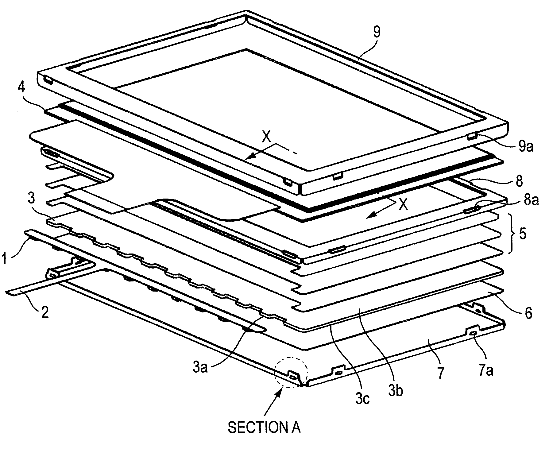
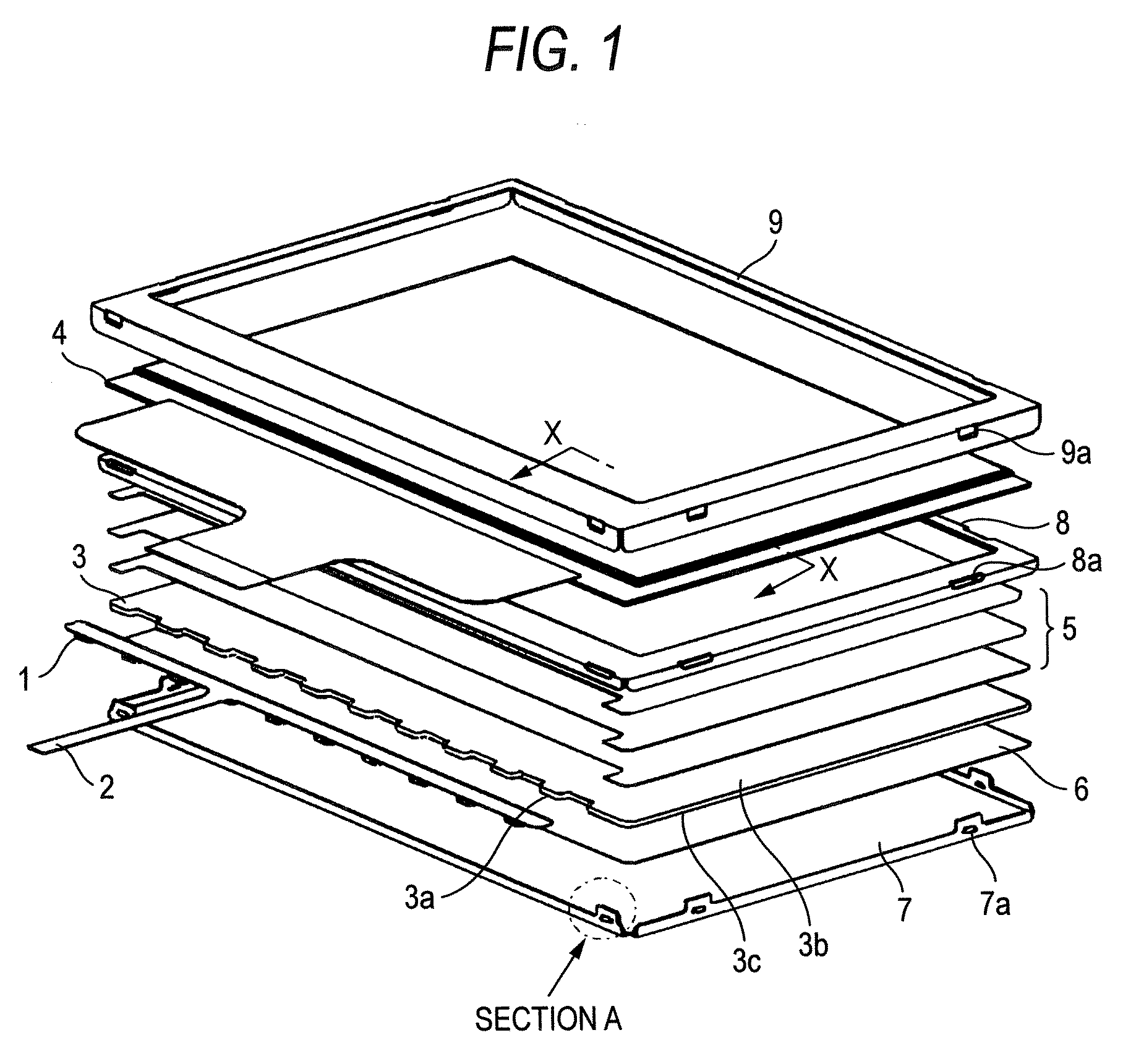
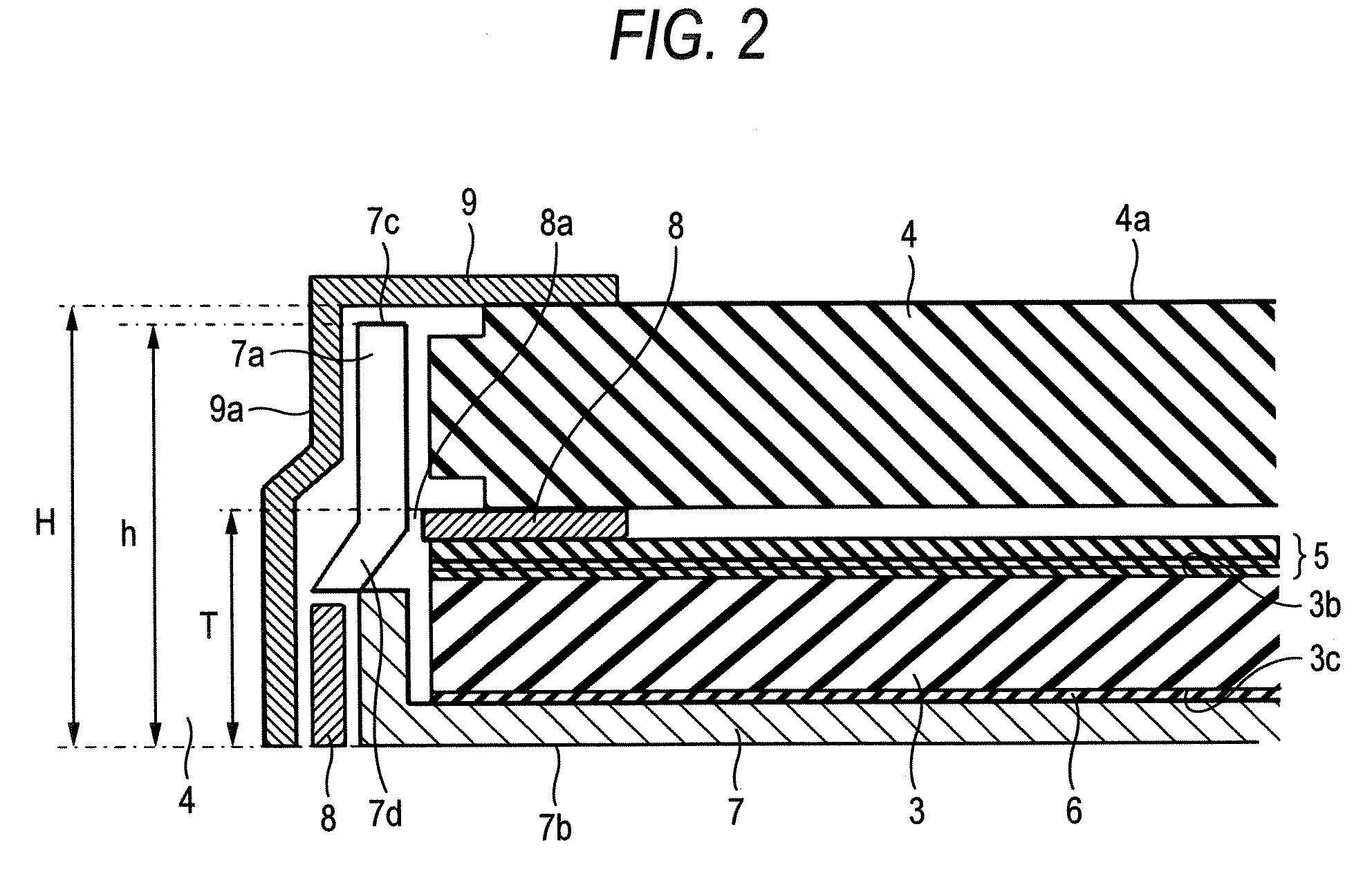
[0017]FIG. 1 is an exploded perspective view of a display device in an embodiment of the invention. FIG. 2 is a cross-sectional view in the X-X direction of a display device made up of the elements shown in FIG. 1. FIG. 3 is a detailed view of Section A shown in FIG. 1.

[0018]Referring to FIGS. 1 through 3, a plurality of light sources 1 using point light sources such as LEDs are arranged at a predetermined spacing and connected to a light source board 2. The light source board 2 is arranged in close proximity to a side 3a of a light guide plate 3. ...


PUM


Abstract

A display device includes: a light source; a light guide plate including a light emitting surface that emits light incident from the light source; a light source board including the light source arranged thereon, the light source board arranged in close proximity to a side surface of the light guide plate; a rear frame arranged to support the light guide plate and including a protruding portion formed on a side surface of the rear frame; a middle frame arranged to support the light guide plate and the rear frame and including a notch portion where the protruding portion of the rear frame penetrate; and a display panel whose horizontal position is regulated by the protruding portion of the rear frame penetrating the notch portion of the middle frame.

Description

CROSS-REFERENCE TO RELATED APPLICATIONS[0001]This application is based upon and claims the benefit of priority from Japanese Patent Application No. 2006-057809, filed on Mar. 3, 2006, the entire contents of which are incorporated herein by reference.BACKGROUND OF THE INVENTION[0002]1. Field[0003]The present invention relates to a display device using a light source board, and manufacturing method thereof.[0004]2. Description of the Related Art[0005]Generally, a display device, for example a display device using liquid crystal, includes a light guide plate arranged on a surface opposite to a liquid crystal panel display surface and a light source such as a light emitting diode (LED) arranged on a side surface of the light guide plate. By propagating light from the light source in the light guide plate and diffusing the light in a diffusion pattern provided in the light guide plate, the light is extracted onto the display surface.[0006]The display device further includes a middle fram...

Claims


Application Information

Patent Timeline
Patent Type & Authority Applications(United States)
IPC IPC(8): F21V7/04
CPCG02B6/005G02B6/0068G02F2201/465G02F2001/133325G02B6/0088G02F1/133325G02F1/1335
Inventor ITO, ATSUSHI
Owner MITSUBISHI ELECTRIC CORP
Why Eureka
Try Eureka