Liquid crystal display with narrow frame area

a liquid crystal display and frame area technology, applied in non-linear optics, instruments, optics, etc., can solve the problems of reducing the effective utilization area of the substrate for display, time-consuming liquid filling method, and damage to liquid crystal materials, so as to narrow down the frame area of the liquid crystal display

Active Publication Date: 2005-05-05
HANNSTAR DISPLAY CORPORATION
View PDF4 Cites 12 Cited by
  • Summary
  • Abstract
  • Description
  • Claims
  • Application Information

AI Technical Summary

Benefits of technology

[0006] It is an object of the present invention to provide a liquid crystal display with a narrow frame area, in which the metal layers formed in the TFT manufacturing process are deposited and patterned in the frame area to form a UV shield. The way is to use the metal layers, which are the same as the scan line metal layers and the data line metal layers, in the frame area and form an integrated black matrix to prevent a light leakage in the frame area. In addition, the seal can be formed in the overlapped area to further narrow down the frame area of the liquid crystal display.

Problems solved by technology

Such liquid filling method is time-consuming and is a waste of liquid crystal.
However, the liquid crystal material would be damaged by the UV light, and hence, the liquid crystal in the active display area 12 must be protected by a UV shield during the exposure to UV light.
Although this way is simple, it has a disadvantage that the seal 15 must be located at the area outside the black matrix 14 so as to be fully exposed to the UV light for solidification.
Therefore, the effective utilization area of the substrate for display is reduced, and is not suitable for use in the portable product, such as a notebook, that demands a narrow frame area.

Method used


Image

  • Liquid crystal display with narrow frame area
  • Liquid crystal display with narrow frame area
  • Liquid crystal display with narrow frame area

Examples


Embodiment Construction

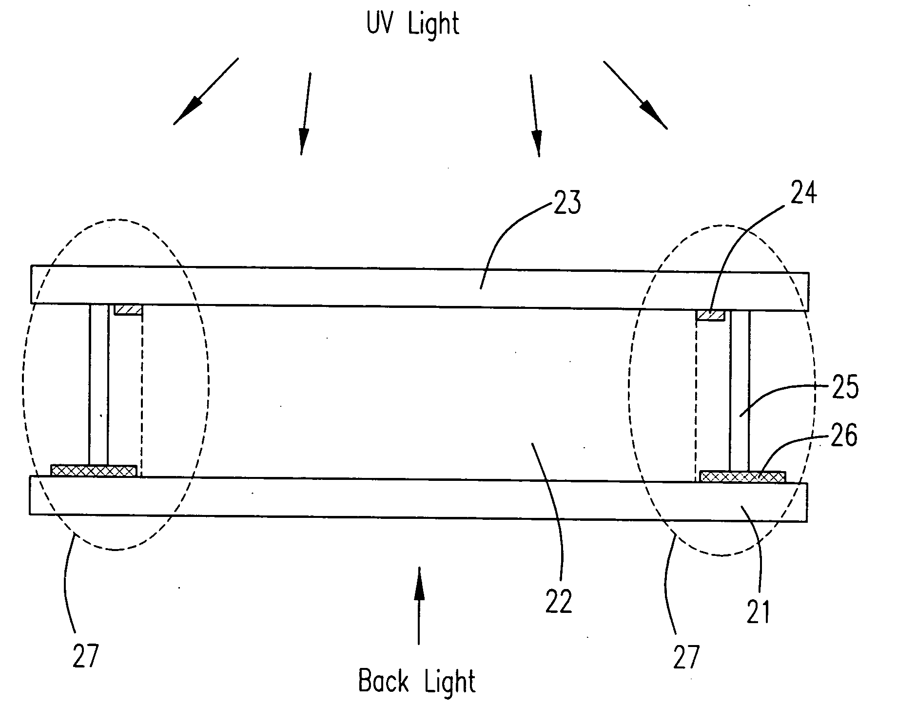
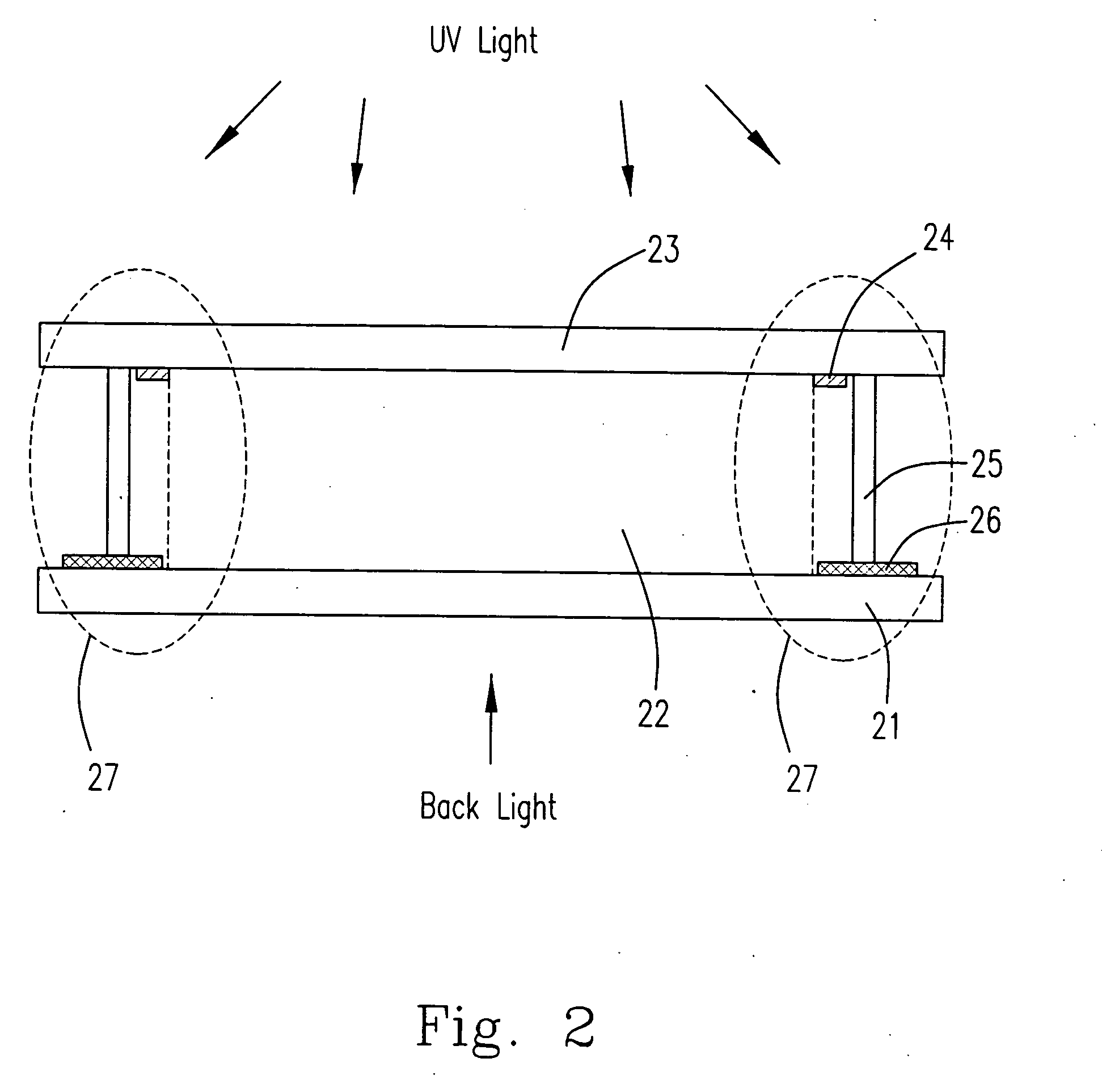
[0034] Please refer to FIG. 2 showing a cross-sectional view of the liquid crystal display formed by the one drop fill (ODF) process according to a preferred embodiment of the present invention. The liquid crystal display includes a first substrate 21, a second substrate 23, and an active display area 22 between the first substrate 21 and the second substrate 23. According to the manufacturing method for the liquid crystal display of the present invention, plural scan line metal (gate metal) layers are formed first on the first substrate 21, and then plural data line metal (source and drain metal) layers are formed on the scan line metal layers. The second substrate 23 is attached to the first substrate 21 via a seal 25, which is coated at an outside periphery of the first substrate and is solidified by a UV light. At least one opaque layer 24, such as a black matrix (BM) or a color filter (CF), is formed on the second substrate 23 at the inside of the seal 25. In which, the color f...


PUM

PropertyMeasurementUnit
opacityaaaaaaaaaa
coloraaaaaaaaaa
areaaaaaaaaaaa

Abstract

The present invention discloses a liquid crystal display with a narrow frame area. The liquid crystal display comprises a first substrate, plural scan line metal layers and plural data line metal layers formed on the first substrate, a second substrate attached to the first substrate by applying a seal at a periphery of one of the first substrate and the second substrate, and an opaque layer formed on the second substrate at the inside of the seal. In which, the scan line metal layers and the data line metal layers extend to the outside of the seal, and overlap with each other to form an integrated black matrix on the first substrate, which overlaps with the opaque layer on the second substrate so as to prevent a light leakage in an overlapped area thereof and narrow down the frame area.

Description

FIELD OF THE INVENTION [0001] The present invention relates to a liquid crystal display, and more particularly to a liquid crystal display with a narrow frame area. BACKGROUND OF THE INVENTION [0002] In the current display industry, the liquid crystal display (LCD) has gradually replaced the cathode ray tube (CRT) to become a mainstream product due to its excellent properties of low radiation and low power consumption. The liquid filling method of the conventional liquid crystal display is to suck up the liquid crystal slowly by capillarity, after the upper and lower substrates are assembled. Such liquid filling method is time-consuming and is a waste of liquid crystal. Therefore, a new liquid filling method of one drop fill (ODF) is developed. The one drop fill (ODF) process is to directly drop the liquid crystal onto the lower substrate, and then assemble the upper and lower substrates. This new process greatly reduces the time and the materials for filling the liquid crystal, and...

Claims


Application Information

Patent Timeline
Patent Type & Authority Applications(United States)
IPC IPC(8): G02F1/1333G02F1/1335G02F1/1339
CPCG02F1/133512G02F2001/133388G02F1/1339G02F1/133388
Inventor CHENG, JIA-SHYONGYANG, CHIEH-HSIUNG
Owner HANNSTAR DISPLAY CORPORATION
Why Eureka
Try Eureka