Drive conversion mechanism enabling constantly meshed gears in a drive input gear train

a conversion mechanism and input gear technology, applied in the direction of gearing details, gearing, transportation and packaging, etc., can solve the problems of time to engage the output gear and drawbacks of lost motion, and achieve the effect of minimal loss of motion and efficiency

Active Publication Date: 2012-06-19
LEXMARK INT INC
View PDF9 Cites 2 Cited by
  • Summary
  • Abstract
  • Description
  • Claims
  • Application Information

AI Technical Summary

Benefits of technology

[0008]The present invention meets this need by providing an innovation in the form of a drive conversion mechanism that enables the provision of constantly meshed gears in the aforementioned input gear train for accommodating directional reversal of rotary input motion by the gear train as a unidirectional rotary output motion is produced by an output shaft of the drive conversion mechanism. The drive conversion mechanism enables the provision of constantly meshed gears in the input gear train, and thus the avoidance of lost motion and time of alternately meshing of gears, by incorporating a pair of clutches each connected to one of two output gears constantly meshed with the aforementioned gear train and arranged about an output shaft in reverse orientations such that the clutches can only drivingly engage the shaft at alternate times, and thus not at the same time, in response to the input gear train reversing its rotational direction, so that the output shaft produces rotary output motion in only a single direction. Thus, the output rotation is always in one direction with minimal lost motion and efficiency as the input rotation may vary between clockwise and counterclockwise rotation. The clutches may take the various forms, for example, a pair of wrap spring clutches which alternately are engaged on the shaft or slip relative thereto or a pair of ball clutches which alternately are engaged on the output shaft, to only transmit output rotation in the one direction.

Problems solved by technology

While this type of drive arrangement is inexpensive, effective and widely used, it has drawbacks of lost motion and time to engage the output gear with the proper one of the idler gears when reversing the direction of the input drive gear.

Method used


Image

  • Drive conversion mechanism enabling constantly meshed gears in a drive input gear train
  • Drive conversion mechanism enabling constantly meshed gears in a drive input gear train
  • Drive conversion mechanism enabling constantly meshed gears in a drive input gear train

Examples


Embodiment Construction

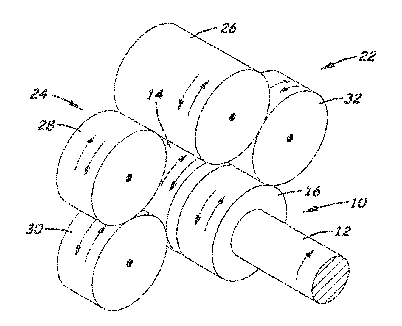
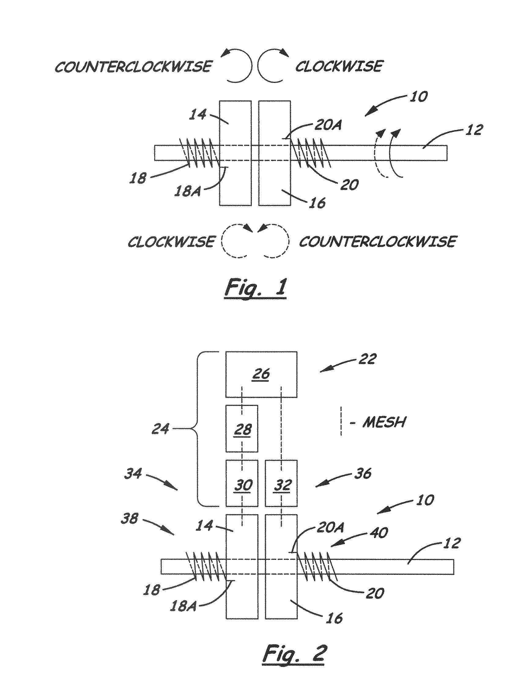
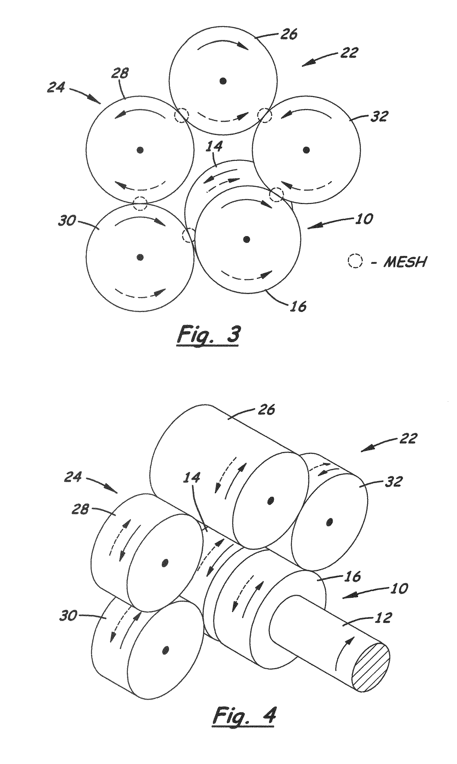
[0017]The present invention now will be described more fully hereinafter with reference to the accompanying drawings, in which some, but not all embodiments of the invention are shown. Indeed, the invention may be embodied in many different forms and should not be construed as limited to the embodiments set forth herein; rather, these embodiments are provided so that this disclosure will satisfy applicable legal requirements. Like numerals refer to like elements throughout the views. Also, to reduce complexity of the drawings, actual teeth on the gears that are meshed are not shown.

[0018]Referring now to FIG. 1, there is illustrated a simplified diagram of a drive conversion mechanism, generally designated 10, in accordance with the present invention. The mechanism 10 includes an output shaft 12, first and second output gears 14, 16, and first and second one-way clutches 18, 20 which, by way of the illustrated example but not for purposes of limitation, may each be in the form of a ...


PUM


Abstract

A drive conversion mechanism includes a rotatably mounted output shaft, a pair of output gears mounted on the output shaft so as to rotate independent of one another and relative to the output shaft and being displaced from each other axially along the output shaft, and a pair of one-way clutches arranged about the output shaft. Each clutch is connected to one of the output gears and extends about the output shaft in respective orientations that are the reverse of each other such that the one-way clutches can only drivingly engage the output shaft at alternate times, and thus not at the same time, so as to cause the output shaft to rotate in a same single direction as the output gears are driven in opposite directions relative to each other by an input train of constantly meshed input drive and idler gears.

Description

CROSS REFERENCES TO RELATED APPLICATIONS[0001]None.BACKGROUND[0002]1. Field of the Invention[0003]The present invention relates generally to drive arrangements in machines, for instances inkjet printers and the like, and, more particularly, to a drive conversion mechanism for enabling constantly meshed gears in a drive input gear train.[0004]2. Description of the Related Art[0005]Consumer inkjet printers typically incorporate one or more drive arrangements which allow reversing of an input while maintaining a unidirectional output. This is done to achieve system efficiency and reduce part count within the machine. Such drive arrangements have been used predominately in sheet feeding pick mechanisms of these machines, but have applications in other areas as well. In a common embodiment, the drive arrangement includes an input gear train of meshed rotary input drive gear and idler gears, usually four, mounted on a plate which idler gears are allowed to rotate or pivot fractionally abo...

Claims


Application Information

Patent Timeline
Patent Type & Authority Patents(United States)
IPC IPC(8): F16H3/00F16D41/04F16H57/00
CPCB41J13/103B41J23/02B65H3/0669F16H3/003B65H2403/42B65H2403/72Y10T74/19605B65H2801/12B65H2403/942Y10T74/19172B65H2220/09
Inventor KLEIN, WILLIAM SCOTT
Owner LEXMARK INT INC
Why Eureka
Try Eureka