Apparatus and method for recording a scene for a plurality of lighting setups using only a portion of each cinematic frame

a technology of lighting setup and camera, applied in the field of illumination and recording scenes can solve the problems of inability to film a motion picture scene using multiple lighting setups, motion artifacts, and often occurring motion artifacts, and achieve the effects of minimal image data storage requirements, minimal motion offset, and efficient recording a scen

Active Publication Date: 2022-02-22
SATELLITE LAB
View PDF6 Cites 0 Cited by
  • Summary
  • Abstract
  • Description
  • Claims
  • Application Information

AI Technical Summary

Benefits of technology

[0031]The apparatus of the invention employs a camera configured to record high-speed frames (also called “micro frames”) only during a portion of each cinematic frame, (also called a “macro frame”), to efficiently record a scene with multiple lighting setups, all in one “take”, with minimal motion offset among the micro frames, and with minimal image data storage requirements.
[0035]Because the micro frames are captured as part of a sequence of micro frames of substantially short time duration relative to each macro frame, the benefits of the invention include minimized motion offset, thereby substantially minimizing the need to employ complex optical flow algorithms to remove motion artifacts.
[0037]In addition, according to the invention, the positions of the light sources are not constrained, permitting more creative expression via freedom to place each light source where needed or desired, thereby facilitating rapid setup and consequent reduced time, difficulty, and expense of filming.
[0042]A plurality of groups / sets of light sources are first positioned in the desired locations, and configurable software in the controller then controls which light sources are fired for each micro frame that is recorded by the camera. Each of the plurality of lighting setups is fired for each cinematic frame. The micro frames corresponding to the lighting setups in each cinematic frame can then be extracted from the entire cinematic frame sequence to create a set of clips of footage. Each clip of footage shows the scene under one lighting setup. These clips of footage can be combined in post-processing for creative or technical flexibility and efficiency.

Problems solved by technology

This is because, with traditional motion picture film technology, it is not possible to film a motion picture scene using multiple lighting setups in only one “take”.
As many movie-goers and cinematographers are aware, the standard cinematic frame rate of 24 FPS is slow enough to cause motion artifacts when movement occurs rapidly within a scene during recording.
Clearly, motion artifacts often occur when the motion is captured at cinematic frame rates having frame durations of 41.6667 milliseconds.
In addition, if there is movement of the subject being filmed during a cinematic frame, the image data captured near the beginning of the cinematic frame of 41.6667 milliseconds will not “line up” with the image data captured near the end of the cinematic frame, thereby causing motion artifacts.
In fact, in the case of rapid subject movement, image data that is captured only a few milliseconds apart may have motion artifacts.
However, high-speed cameras generate much more image data than a standard cinematic frame rate camera.
Therefore, despite the advantages of using a high speed camera, a serious drawback to such a camera is the amount of memory needed for image data storage when using a high-speed frame rate, versus filming at the standard cinematic frame rate of 24 FPS.
However, the apparatus of Debevec has disadvantages.
If the high-speed frames are not corrected for movement within the duration of a cinematic frame, after being de-multiplexed and before being superimposed to form a cinematic frame, the resulting cinematic frame can show motion artifacts.
These intra-cinematic frame delays can cause motion artifacts.
After the recorded data is de-multiplexed, complex and burdensome optical flow algorithms are often required to remove these motion artifacts.
A high-speed camera with a constant frame rate must record a burdensomely large quantity of image data, because each cinematic frame requires capturing a large amount of high-speed frame image data.
The resulting overabundance of image data is costly to store.
As a result, the maximum length of time of the recording may be limited to only a few seconds, unless costly image data storage equipment is used.
Further, to reduce the image data storage requirements, the quality of the stored images may need to be reduced, providing film footage with lower than ideal resolution and image quality.
In the apparatus of Debevec, the complexity of the lighting setup increases the time, difficulty, and expense of filming.

Method used


Image

  • Apparatus and method for recording a scene for a plurality of lighting setups using only a portion of each cinematic frame
  • Apparatus and method for recording a scene for a plurality of lighting setups using only a portion of each cinematic frame
  • Apparatus and method for recording a scene for a plurality of lighting setups using only a portion of each cinematic frame

Examples


embodiment 100

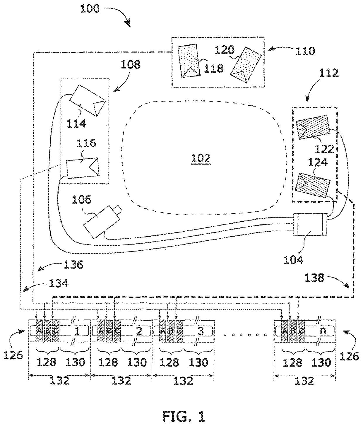
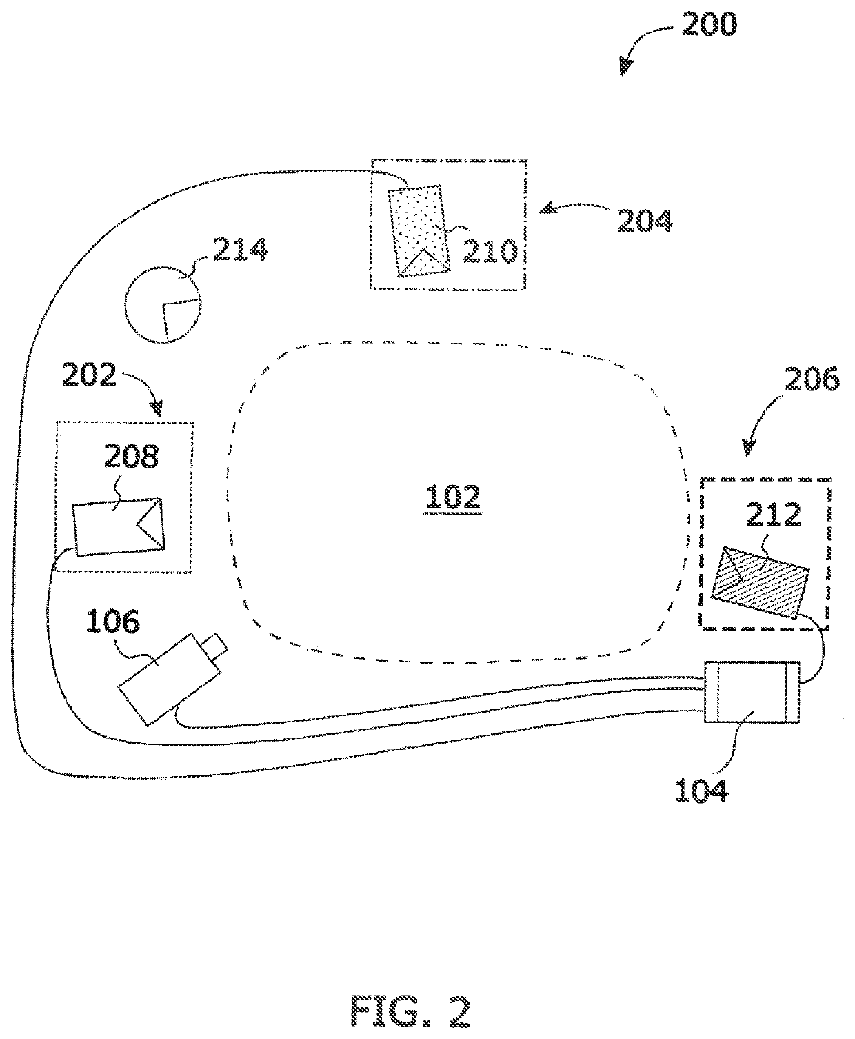
[0075]With reference to FIG. 1, a schematic diagram is presented of an apparatus 100 for illuminating and recording a scene 102 using three lighting setups 108, 110, 112. In this embodiment 100, each lighting setup 108, 110, 112 has two light sources that are capable of providing strobed light. The apparatus 100 includes a controller 104 in communication with a camera 106 configured to record the scene 102.

[0076]The controller 104 is also in communication with lighting equipment consisting of: a light source 114, a light source 116, a light source 118, a light source 120, a light source 122, and a light source 124. The light sources are grouped into three lighting setups: a first lighting setup 108 consisting of light source 114 and light source 116, a second lighting setup 110 consisting of light source 118 and light source 120, and a third lighting setup 112 consisting of light source 122 and light source 124.

[0077]Each light source that is capable of providing strobed light can b...

case 1

[0122]

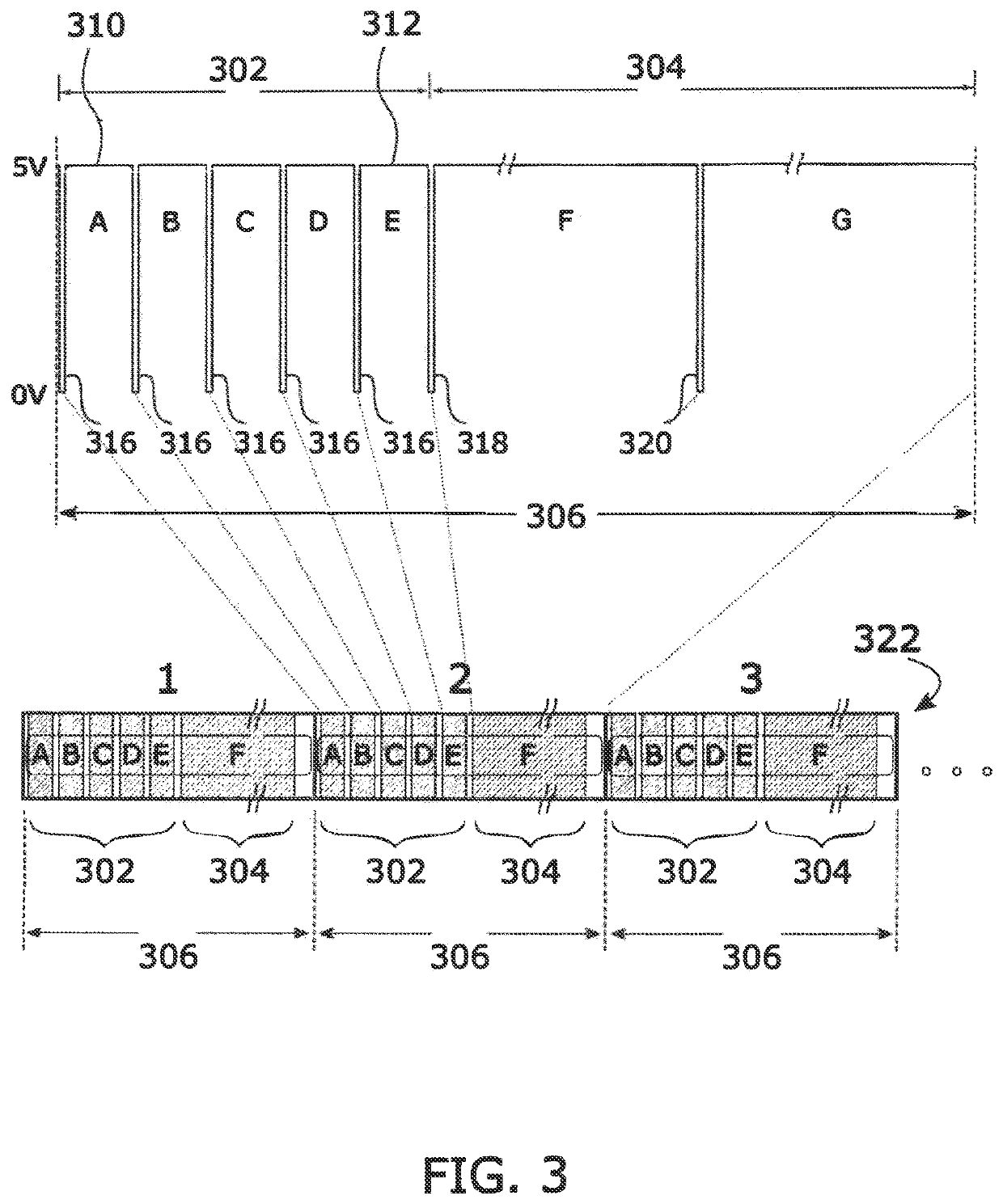
[0123]Duration of micro frames 302+Duration of F=(Macro Frame Duration 306) / 2

[0124]Duration of G=(Macro Frame Duration 306) / 2

case 2

[0125]

[0126]Duration of micro frames 302+Duration of G=(Macro Frame Duration 306) / 2

[0127]Duration of F=(Macro Frame Duration 306) / 2

[0128]One possible case with a single long frame F only, for example:

[0129]Duration of micro frames 302+Duration of F=Macro Frame Duration 306

[0130]Thus, there can be a long frame F wherein ambient continuous light is captured, and there can be a long frame G wherein ambient continuous light is captured. It is also possible that there are no long frames F or G, and the camera does not record light during 304, only during 302. It is also possible for ambient continuous light to be captured during a long frame F, and there would be no long frame G.

[0131]This embodiment includes five micro frame low trigger signals A, B, C, D, E 316 that the camera 106 sends to the controller 104 (shown in FIG. 1) at the beginning of each micro frame A, B, C, D, and E. In this embodiment, these five micro frame low trigger signals A, B, C, D, E 316 communicate to the contro...


PUM


Abstract

Apparatus for recording a scene using a plurality of lighting setups in rapid sequence to concurrently record a plurality of motion picture clips of the scene, one motion picture clip for each lighting setup, the plurality of clips together exhibiting negligible motion offset. The apparatus includes a plurality of light sources, a controller to define the plurality of lighting setups using the plurality of light sources and to actuate the lighting setups in sequence, a camera to capture a sequence of micro frames showing the scene illuminated by each one of the plurality of lighting setups in sequence during each micro frame, and optionally a processing module to process the sequence of micro frames to generate a motion picture clip of the scene for each of the lighting setups. The duration of the micro frame sequence is short enough to minimize the need for an algorithm for removing motion artifacts.

Description

FIELD OF THE INVENTION[0001]This invention relates generally to illuminating and recording scenes using multiple lighting setups, and particularly to producing motion picture footage of a scene for each of a plurality of lighting setups.BACKGROUND OF THE INVENTION[0002]Lighting Setups[0003]In the film industry, it is common to use different lighting setups to add creative and / or technical value to a motion picture. It can be advantageous to film the same scene under different lighting conditions, and later choose the most desirable lighting effect for the scene.[0004]Furthermore, it can be desirable to have the option of combining different lighting setups in post-production. Traditionally, multiple “takes” are filmed using different lighting setups, and are then edited to restore the continuity of a motion picture scene. This is because, with traditional motion picture film technology, it is not possible to film a motion picture scene using multiple lighting setups in only one “tak...

Claims


Application Information

Patent Timeline
Patent Type & Authority Patents(United States)
IPC IPC(8): H04N5/232H04N5/235
CPCH04N5/23277H04N5/2354H04N23/56H04N23/60H04N23/74H04N23/90H04N23/6845
Inventor VAN DE ROER, CARLORUTHERFORD, STUART
Owner SATELLITE LAB
Why Eureka
Try Eureka