Thermode cleaning method

a cleaning method and cleaning method technology, applied in the field ofthermode cleaning, can solve the problems of reducing the reliability of the soldering process or generating additional particulates that may contaminate the local environment, affecting prolonging the interval between normal mechanical scrubbing cycles, so as to improve the useful life of the thermode, reduce the time to complete, and reduce the amount of additional tooling or motion

Active Publication Date: 2011-09-13
ATS AUTOMATION TOOLING SYSTEMS
View PDF29 Cites 0 Cited by
  • Summary
  • Abstract
  • Description
  • Claims
  • Application Information

AI Technical Summary

Benefits of technology

This application relates to a method of cleaning a thermode that is intended to take less time to complete, require minimal additional tooling or motion and improve the useful life of the thermode. This cleaning method is also intended not to reduce the soldering process reliability or generate additional particulates that may contaminate the local environment.

Problems solved by technology

This cleaning method is also intended not to reduce the soldering process reliability or generate additional particulates that may contaminate the local environment.
This method may result in a longer interval between normal mechanical scrubbing cycles and a substantial increase in thermode life.

Method used


Image

  • Thermode cleaning method
  • Thermode cleaning method
  • Thermode cleaning method

Examples


Embodiment Construction

In one aspect herein, a method for cleaning a thermode tip comprising applying an energy pulse to the thermode tips is disclosed

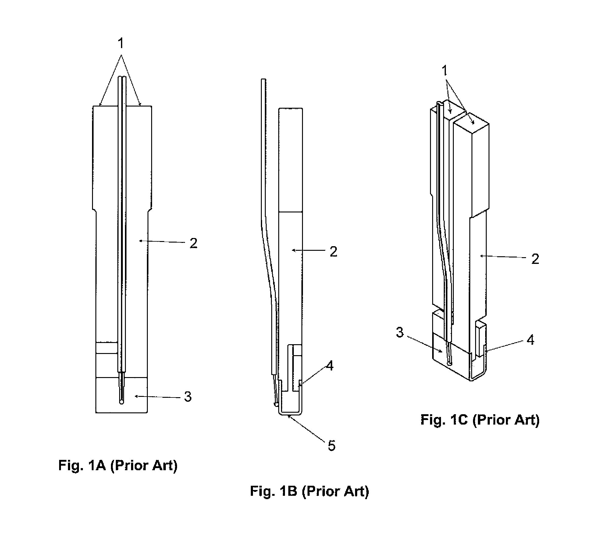
A typical thermode construction is illustrated in FIG. 1A, 1B and 1C. The thermode includes terminals (1) where the power is applied and a shank (2) for supporting and conducting current to a tip (3). A transition zone (4) allows for the joining of the tip (3) to the shank (2). The working surface (5) is the portion of the tip, which comes in contact with the part bond area. The tip (3) and, in particular, the working surface (5) generally require cleaning due to residue build-up, a by-product of running soldering cycles.

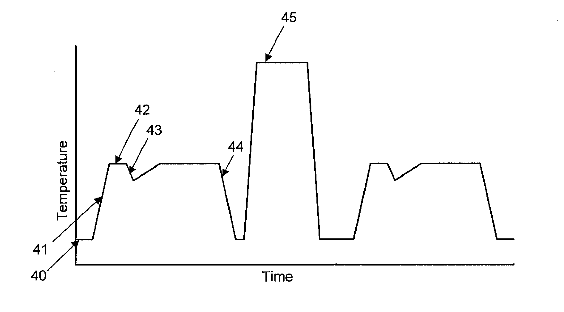
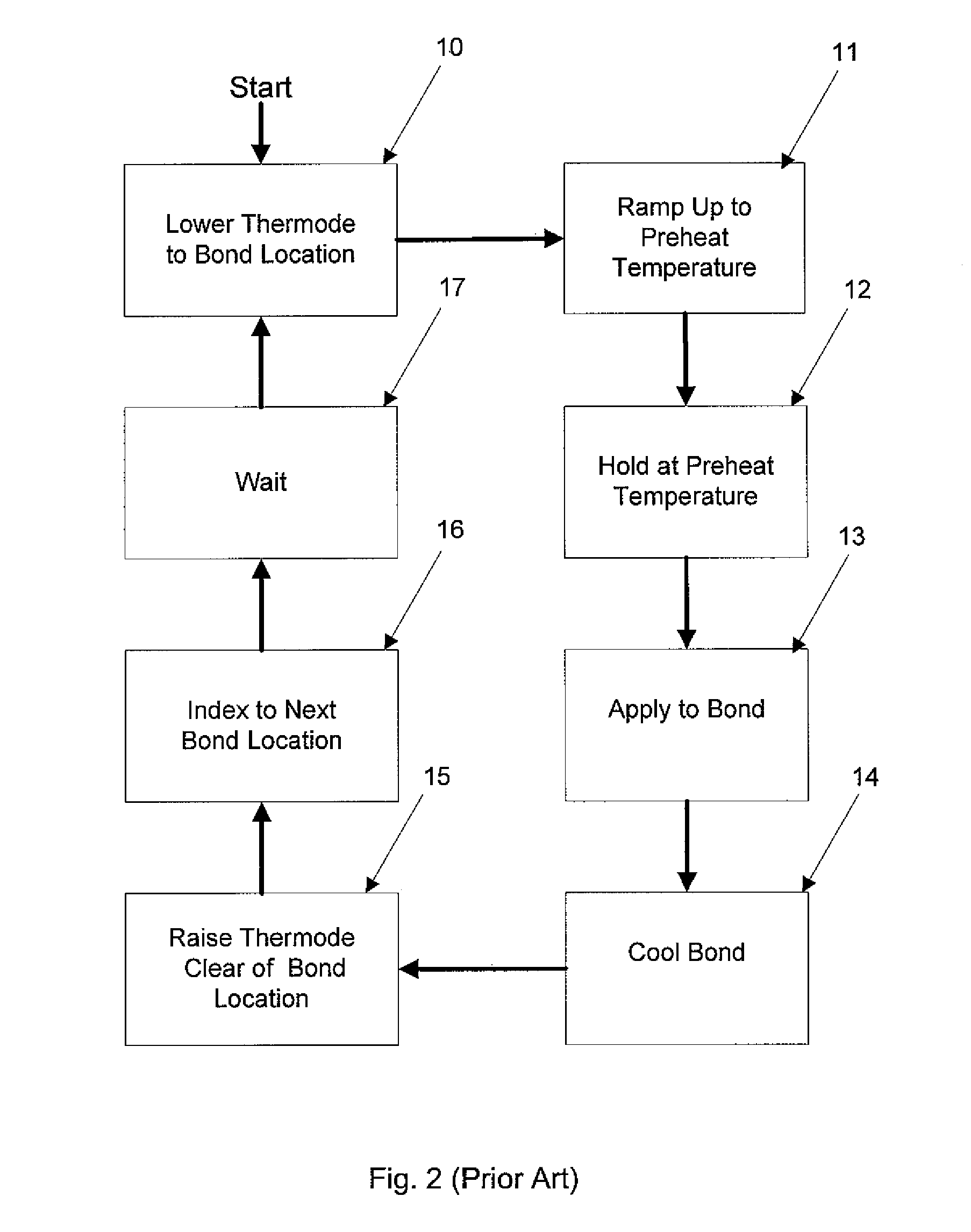
FIG. 2 illustrates a typical thermode reflow soldering process. The thermode is first lowered to the bond area (10). The thermode is then ramped up to a preheat temperature (11) to the required temperature level for the bond. Once the preheat temperature is achieved the thermode holds at this temperature (12). The application of the thermod...


PUM

PropertyMeasurementUnit
temperatureaaaaaaaaaa
timeaaaaaaaaaa
energyaaaaaaaaaa

Abstract

A method for cleaning a thermode tip including applying an energy pulse to the thermode tip. The energy pulse involves raising the temperature of the thermode tip higher than the working temperature of the thermode tip. A method for cleaning a thermode tip may include periodically performing a predetermined number of soldering cycles at a working temperature; and applying an energy pulse to the thermode tip.

Description

FIELDThe present document relates generally to thermode cleaning. More particularly, the present document relates to a cleaning method for cleaning thermode soldering tips.BACKGROUNDThermodes are devices used for local application of heat and pressure, typically in soldering applications known as ‘Hot-bar reflow soldering’. Once the thermode is brought into contact with a desired location, localized heating is produced by direct resistance heating of the tip of the thermode. The ‘soldering gun’ is a common example.The main advantage of thermode soldering is the very rapid temperature change (up to 1000° Celsius per second) with precise control over the temperature while the component parts are being mechanically held by thermode contact pressure. Also, since the hottest portion of the thermode is typically in direct contact with the part bond area, efficient heat transfer occurs and rapid heating of the item is possible. The bond area is the area(s) of the part being processed where...

Claims


Application Information

Patent Timeline
Patent Type & Authority Patents(United States)
IPC IPC(8): B23K31/02
CPCB08B7/0071B23K1/206B23K3/08B23K3/03B08B7/00
Inventor DUNLOP, JOEL ANTHONY PATRICKABU-EL-MAGD, ALIYUEN, KA MING TIMBERWILSON, ALLISONSPITHOFF, ANTHONYSTROBL, WALTERKRAUSE, ARNO
Owner ATS AUTOMATION TOOLING SYSTEMS
Why Eureka
Try Eureka