Inhaler

a technology of inhaler and inhaler body, which is applied in the field of inhalers, can solve the problems of inhaler disadvantage of relative complexity of manufacture, contaminating the environment, and affecting the safety of inhalers, and achieves the effect of overcompensating or substantially reducing the disadvantages

Inactive Publication Date: 2012-06-19
BRIN TECH INT
View PDF12 Cites 54 Cited by
  • Summary
  • Abstract
  • Description
  • Claims
  • Application Information

AI Technical Summary

Benefits of technology

[0007]There has now been devised a form of DPI device which is particularly suitable for the delivery of single doses of medicament, and which overcomes or substantially mitigates disadvantages associated with known forms of inhaler.
[0013]Where, as is preferred, the dispensing region is of only slightly greater dimension than the container, when the medicament container is in the second position there is only a small clearance between the medicament container and the walls of the air passageway. In particular, the clearance may be 2 mm or less, more preferably 1 mm or less, eg in the range 0.05 mm to 1 mm, more preferably 0.1 mm to 0.5 mm. The presence of such a small gap between the medicament container and the surrounding walls of the air passageway offers numerous advantages. In particular, air passing around the medicament container is caused to accelerate, which results in shearing forces being applied to the entrained medicament, thereby breaking up medicament agglomerates and increasing the fine particle fraction of the medicament. The medicament may also be drawn from the medicament container steadily, over a period of time approximating to the full period over which inhalation occurs, rather than being dispensed immediately, as a bolus.
[0018]In the event that the airflow through the device should be reversed, for instance as a result of the user mistakenly exhaling through the device, the medicament container is displaced back towards the first position, and may then effectively occlude the air passageway, preventing or reducing the release of medicament into the atmosphere.
[0020]The device may be manufactured from materials conventionally utilised in inhalation drug delivery devices. For reasons of cost and manufacturing convenience, the device is most preferably manufactured by injection moulding in plastics material. Examples of suitable plastics materials include polycarbonate, polypropylene and polyethylene. Metals may also be used to form all or part of the device. Examples of suitable metals include aluminium and stainless steel. The device may be formed as a single injection-moulded component, or it may comprise a plurality of components that are subsequently bonded or otherwise connected together. An advantage of the use of plastics materials for the inhaler is that transparent materials may be used, enabling visualisation of the medicament container in the dispensing region. If the container too is of transparent material then it becomes possible to verify complete emptying of the container by visual inspection. Injection moulding is also a high precision manufacturing method, and so facilitates production of the inhaler with closely defined dimensions for the air passageway and in particular the air gap between the base of the medicament container and the adjacent surfaces of the dispensing region.
[0023]The medicament container is most preferably circular in cross-section, and most commonly generally cylindrical, taking the form of a drum. The drum may be relatively squat, having a depth that is of a similar magnitude, or is less than, its diameter. The depth of the container is generally not greater than 2.0 times, and is preferably not greater than 1.5 times, and is more preferably less than, its diameter. The upper and lower faces of the container may be flat or substantially flat or one of the faces may be flat and the other convex or domed in form. The latter arrangement may be particularly advantageous, in that a convex or domed roof of the medicament container facilitates occlusion of the air passageway in the event that the medicament container is urged back towards the second position, eg by the user exhaling into the device (by facilitating engagement of the medicament container with the opening from which it is released when displaced from the first to the second position). Such a convex or domed roof may also facilitate displacement of the medicament container from the first position to the second position.

Problems solved by technology

Otherwise, disposal of the device could lead to contamination of the environment and the risk that the devices could be subject to abuse.
Such a risk may be particularly pertinent in the case of a device that has been used for the administration of a highly potent and / or addictive medicament, or one that is dangerous when not properly used.
Such an inhaler suffers from the disadvantage of relative complexity of manufacture, arising from the fact that the inhaler body has to be assembled around the capsule.
As a result, emptying of the capsule may not be as effective as would be desired, which may result in underdosing and also potentially dangerous medicament residues being discarded with the used inhaler.
It is mentioned that movement of a medicament container, as occurs in other forms of inhaler, eg those disclosed in WO-A-98 / 26828, may be undesirable as it may be audible.

Method used


Image

  • Inhaler
  • Inhaler
  • Inhaler

Examples


first embodiment

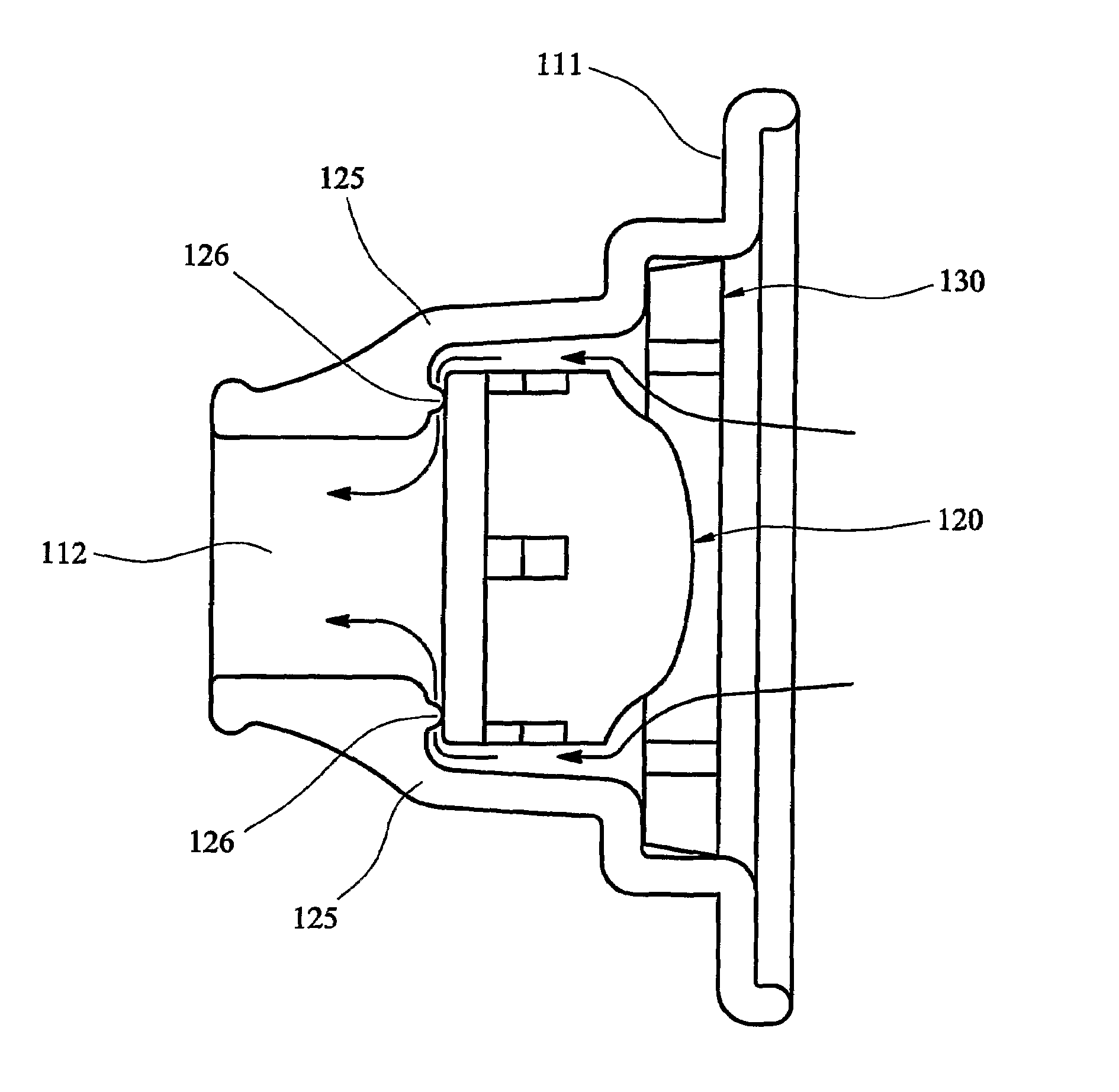
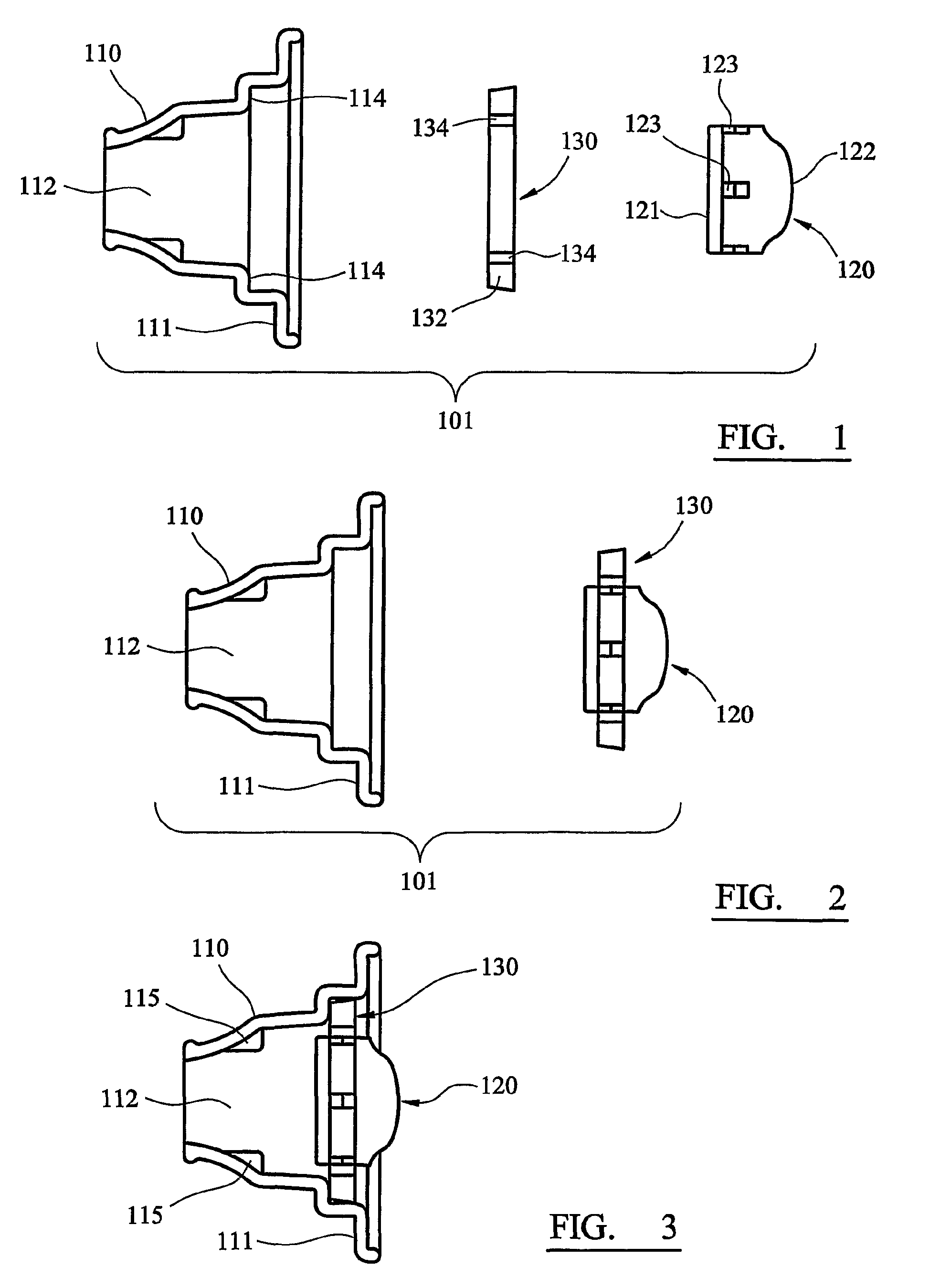
[0046]Referring first to FIGS. 1 to 6, a disposable, unit dose dry powder inhaler according to the invention is generally designated 101. The inhaler 101 comprises three components: a main body 110, a medicament container 120 and a sealing ring 130.

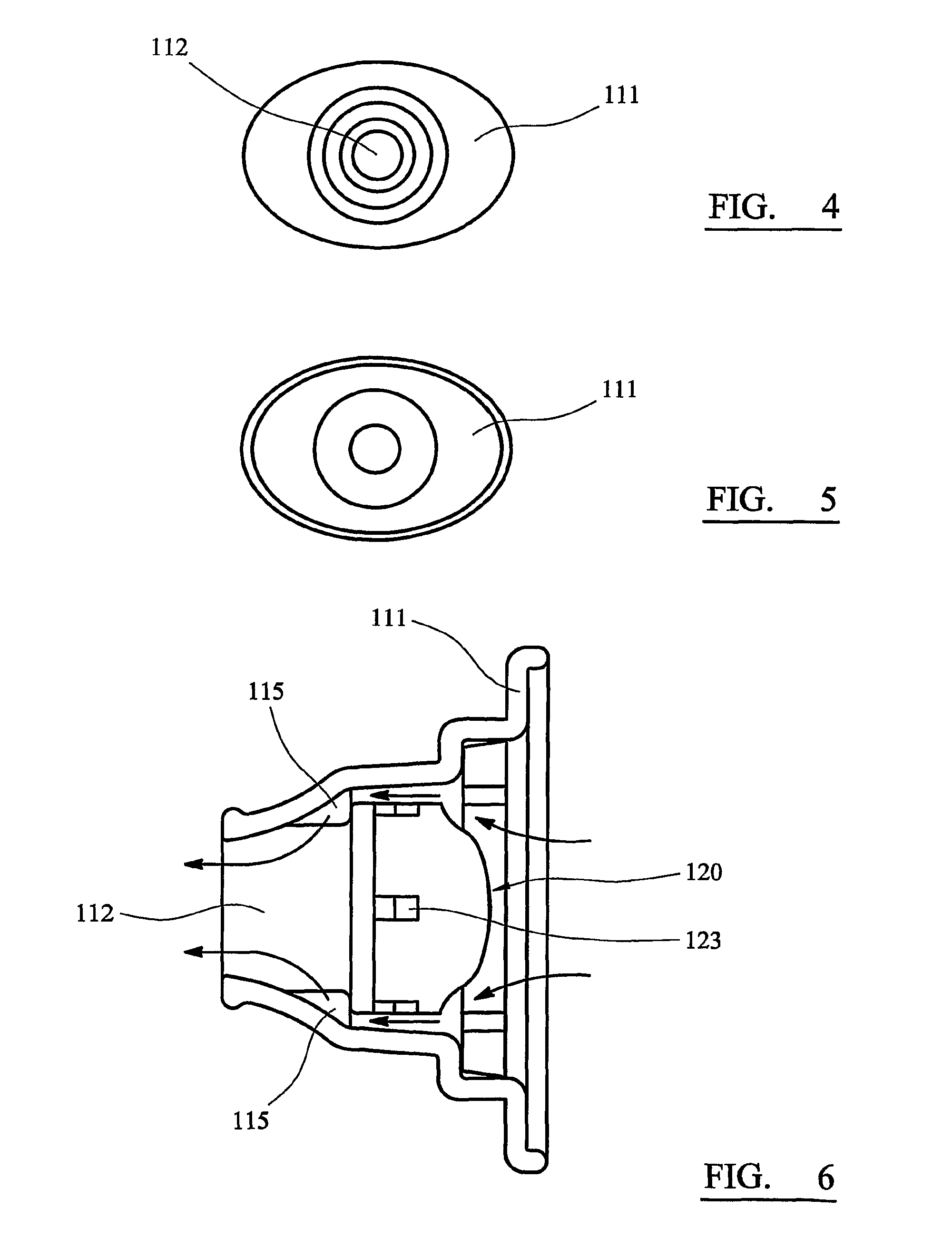
[0047]The main body 110 is formed as a unitary component by injection moulding in plastics material. The body 110 comprises an ovoid plate 111 from which a hollow, generally conical or funnel-shaped mouthpiece 112 is upstanding. The mouthpiece 112 is circular in cross-section, the left-hand (as viewed in FIGS. 1 to 3) part of the mouthpiece 112 being tapered to a form that can conveniently be inserted between a user's lips.

[0048]The medicament container 120 has the form of a cylindrical drum, the base 121 of which (the left-hand end as viewed in FIG. 1) is flat, and the roof 122 of which (the right-hand end) is domed. A number of apertures 123 are equiangularly spaced around the cylindrical surface of the container 120. In the illustrated...

second embodiment

[0057]The embodiment shown in FIG. 7 is broadly similar to that of FIGS. 1 to 6, and corresponding parts are indicated by the same reference numerals. In the second embodiment, however, the abutments 115 are replaced by a circumferential shoulder 125, from which several small lugs 126 are upstanding. The lugs 126 define a precise separation between the shoulder 125 and the base of the medicament container 120.

[0058]Turning now to FIGS. 8 and 9, a third embodiment of an inhaler according to the invention is generally designated 201, and is intended for the administration of powdered medicament by nasal inhalation. The inhaler 201 is broadly similar in construction to the first embodiment described above, in that it comprises a main body 210, a medicament container 220 that may in fact be identical to that of the first embodiment, and a sealing ring 230 that may also be identical to that of the first embodiment. The principal difference between the third embodiment 201 and the first 1...

fourth embodiment

[0059]an inhaler according to the invention, generally designated 301, and depicted in FIGS. 10 to 13, is constructed in the form of a syringe. In particular, the inhaler 301 comprises an elongate, tubular body 305, one end of which (the right-hand end, as viewed in the Figures) is formed with an integral flange 306, by which the inhaler 301 can be gripped and operated, as described below.

[0060]A plunger 310 is mounted for sliding movement within the tubular body 305. The tip of the plunger 310 is formed with a recess 312, the mouth of which is closed by a closure disc 316 that engages the recess 312 with a snap fit. The recess 312 and the closure disc 316 constitute a medicament container that holds a unit dose of medicament. Dispensing apertures 314 are formed in the medicament container, at the junction of the walls of the recess 312 and the closure disc 316. The external walls of the recess 312 and the closure disc 316 are dimensioned to have a sealing fit with the internal wall...


PUM


Abstract

A dry powder inhaler (101) comprises an inhaler body (110), including an air passageway, and a medicament container (120). The medicament container (120) holds a dose of medicament and is provided with at least one dispensing aperture (123) through which the medicament may be drawn from the medicament container (120). The medicament container (120) is displaceable from a first position, in which the dispensing aperture (123) is occluded, to a second position, in which the dispensing aperture (123) is open and air is able to flow along the air passageway. When the medicament container (120) is in the first position, the air passageway is occluded by the medicament container (120).

Description

CROSS-REFERENCE TO RELATED APPLICATION[0001]The present application claims priority under 35 U.S.C. §371 to PCT / GB2007 / 050359, filed Jun. 26, 2007.FIELD OF THE INVENTION[0002]This invention relates to an inhaler, ie to a device for the administration of powdered medicament by inhalation.BACKGROUND OF THE INVENTION[0003]The administration of medicaments by inhalation is well known. Such medicaments are often administered in the form of solid powders. Pressurised metered dose inhalers (MDIs) are one well-known form of administration, but concerns about the environmental effects of the propellants used in such systems have lead to increased attention on so-called dry powder inhalers (DPIs). In such inhalers, a dose of powdered medicament is entrained in a swirling airflow and inhaled, the swirling airflow normally being created by the act of inhalation.[0004]Many DPIs are configured for repeated use, ie for the administration of repeated doses of medicament to a patient. However, for m...

Claims


Application Information

Patent Timeline
Patent Type & Authority Patents(United States)
IPC IPC(8): A61M16/00
CPCA61M15/0028A61M15/0003A61M2202/064A61M2205/071
Inventor CHAWLA, BRINDA PAUL SINGH
Owner BRIN TECH INT
Why Eureka
Try Eureka