Knuckle formed from pivot pin and kidney core and isolated finger core

a technology of pivot pin and kidney core, which is applied in the manufacture of railway coupler knuckles, foundry patterns, manufacturing tools, etc., can solve the problems of increasing the risk of failure of the knuckle during use, and affecting the use of the knuckl

Active Publication Date: 2012-06-19
BEDLOE IND LLC
View PDF204 Cites 36 Cited by
  • Summary
  • Abstract
  • Description
  • Claims
  • Application Information

AI Technical Summary

Problems solved by technology

Many knuckles fail from internal and / or external inconsistencies in the metal through the knuckle.
If one or more cores move during the casting process, then some knuckle walls may end up thinner than others resulting in offset loading and increased failure risk during use of the knuckle.
These multiple, thin ribs are known to be a source of premature failure of the couple knuckles so designed.

Method used


Image

  • Knuckle formed from pivot pin and kidney core and isolated finger core
  • Knuckle formed from pivot pin and kidney core and isolated finger core
  • Knuckle formed from pivot pin and kidney core and isolated finger core

Examples


Embodiment Construction

[0027]In some cases, well known structures, materials, or operations are not shown or described in detail. Furthermore, the described features, structures, or characteristics may be combined in any suitable manner in one or more embodiments. It will also be readily understood that the components of the embodiments as generally described and illustrated in the Figures herein could be arranged and designed in a wide variety of different configurations.

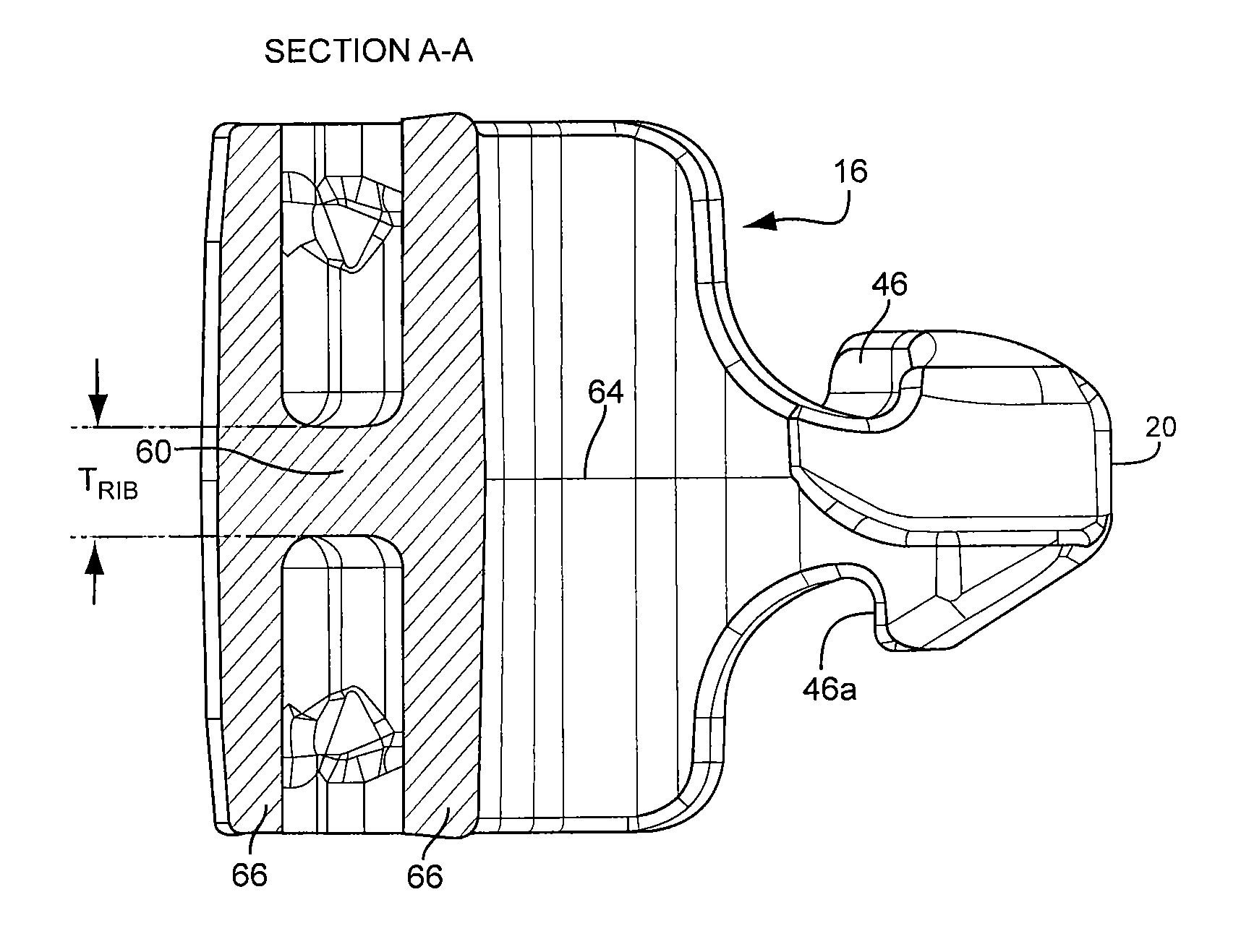
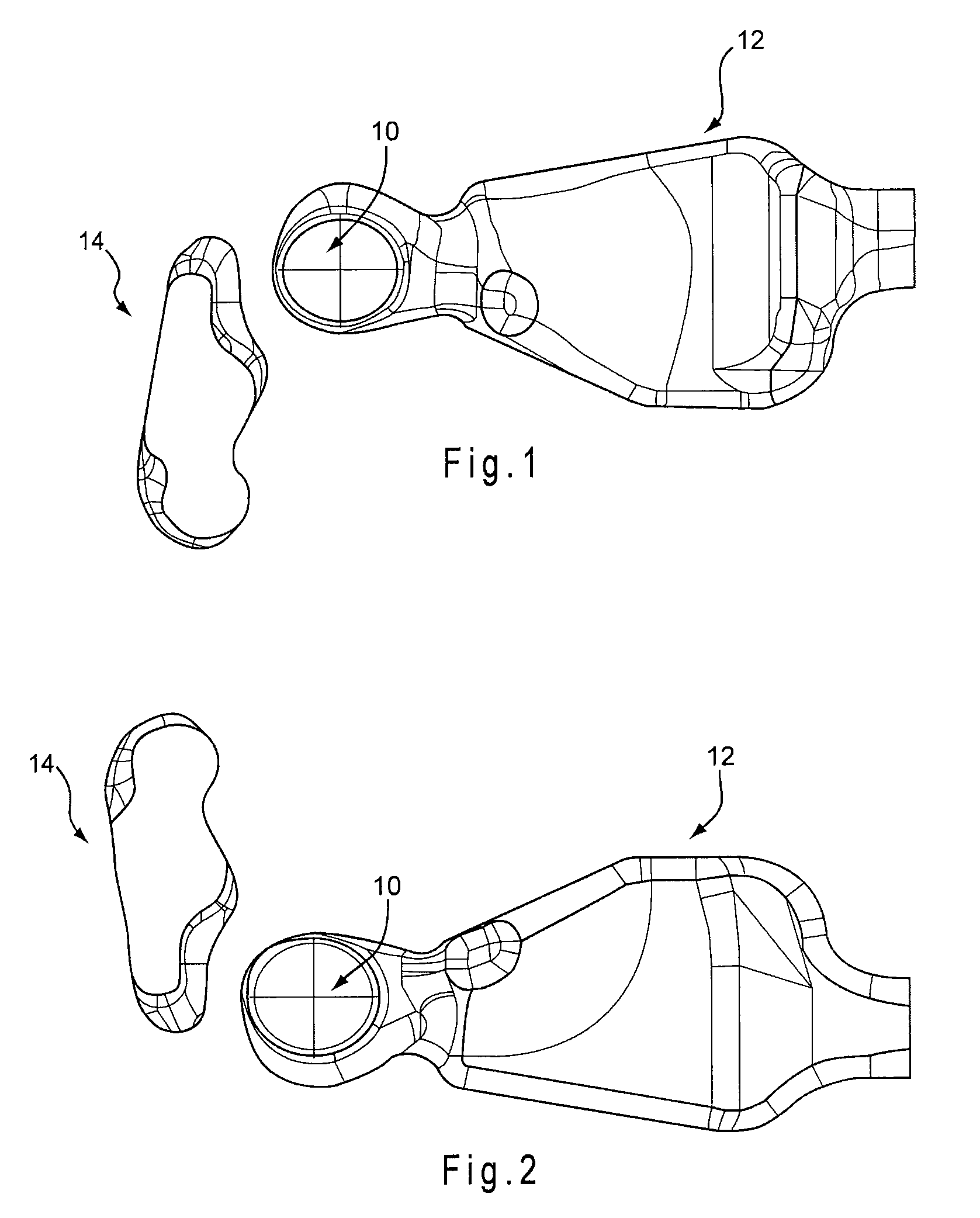
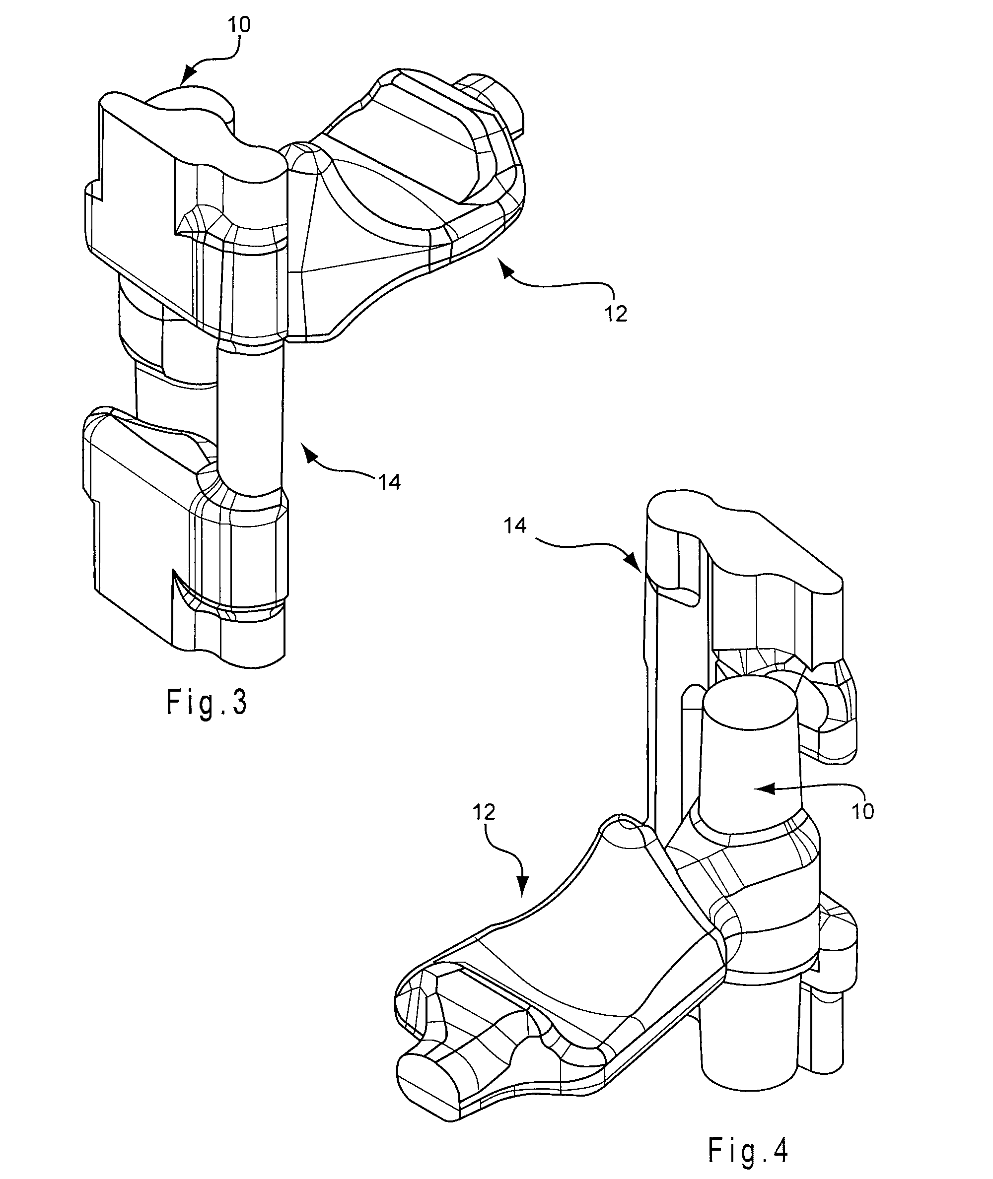
[0028]Referring to FIGS. 1-4, the present embodiments of a railroad coupler knuckle combine a pivot pin core 10 and a kidney core 12 into a first core. A second core is an isolated finger core 14, seen best in FIG. 3 with a unique shape having a large core footprint. The enlarged core footprint improves stabilization of the finger core 14 within the cope and drag mold portions (FIG. 14) during the molding process. Accordingly, the improved stabilization helps to prevent movement during the molding process, thereby helping to insure the i...


PUM

PropertyMeasurementUnit
perimeteraaaaaaaaaa
thickaaaaaaaaaa
strengthaaaaaaaaaa

Abstract

A method for manufacturing a railcar coupler knuckle includes providing cope and drag mold portions having internal walls defining at least in part perimeter boundaries of a knuckle mold cavity; positioning a first internal core within either the cope mold or the drag mold portions, the first internal core configured to define a kidney cavity and a pivot pin hub as a single void within the knuckle; positioning a second internal core within either the cope mold portion and the drag mold portion, the second internal core configured to define a finger cavity; closing the cope and drag mold portions with the two internal cores therebetween; and at least partially filling the mold cavity with a molten alloy, the molten alloy solidifying after filling to form the knuckle, wherein the first internal core defines the kidney cavity and the pivot pin hub of the coupler knuckle, and wherein the second internal core defines the finger cavity of the knuckle.

Description

RELATED APPLICATIONS[0001]This application claims priority to U.S. provisional application Ser. Nos. 61 / 055,459 filed May 23, 2008, and 61 / 055,805 filed May 23, 2008, the disclosures of which are incorporated by reference herein in their entirety.BACKGROUND[0002]1. Technical Field[0003]The present embodiments relate generally to the field of railroad couplers, and more specifically, to the manufacturing of a railway coupler knuckle.[0004]2. Related Art[0005]Railcar couplers are disposed at each end of a railway car to enable joining one end of such railway car to an adjacently disposed end of another railway car. The engageable portion of each of these couplers is known in the railway art as a knuckle.[0006]Typically a knuckle is manufactured with three cores, commonly referred to as a finger core in the front portion of the knuckle, pivot pin core in the center of the knuckle, and a kidney core at the rear of a knuckle. The finger core and kidney core reduce the weight of the knuck...

Claims


Application Information

Patent Timeline
Patent Type & Authority Patents(United States)
IPC IPC(8): B22D33/04
CPCB22C9/103B61G3/04
Inventor MARCHESE, THOMAS A.SMERECKY, JERRY R.
Owner BEDLOE IND LLC
Why Eureka
Try Eureka