
Clamp and lock permanent magnets within a rotating electrical machine using pitched focused flux magnets

a technology of focused flux and permanent magnets, which is applied in the direction of rotating parts of magnetic circuits, magnetic circuit shapes/forms/construction, cooling/ventilation arrangements, etc., can solve the problem of low surface loss self-heating of focused flux machines and surface mount machines, and achieve the effect of improving rotor cooling

Active Publication Date: 2012-06-19
POTENCIA IND LLC
View PDF2 Cites 2 Cited by
  • Summary
  • Abstract
  • Description
  • Claims
  • Application Information

AI Technical Summary

Benefits of technology

"The patent aims to improve the mounting of permanent magnets on the surface of an electrical machine's rotor, enhance rotor cooling, and improve the assembly of the machine. The technical effects of the invention include improved performance and efficiency of the electrical machine."

Problems solved by technology

Further, surface loss self-heating of focused flux machines are far lower than surface mount machines due to the reduced exposure of the magnet poles to induced flux variations.
One of the manufacturing issues related to focused flux machines is the mounting of the magnets to the rotor in a manner that contains the centripetal forces on the magnets due to the rotor rotation in normal operation.

Method used


Image

  • Clamp and lock permanent magnets within a rotating electrical machine using pitched focused flux magnets
  • Clamp and lock permanent magnets within a rotating electrical machine using pitched focused flux magnets
  • Clamp and lock permanent magnets within a rotating electrical machine using pitched focused flux magnets

Examples


Embodiment Construction

[0022]In the following description of the present invention, reference is made to the accompanying drawings, which form a part thereof, and in which are shown, by way of illustration, exemplary embodiments illustrating the principles of the present invention and how it may be practiced. It is to be understood that other embodiments may be utilized to practice the present invention and structural and functional changes may be made thereto without departing from the scope of the present invention.

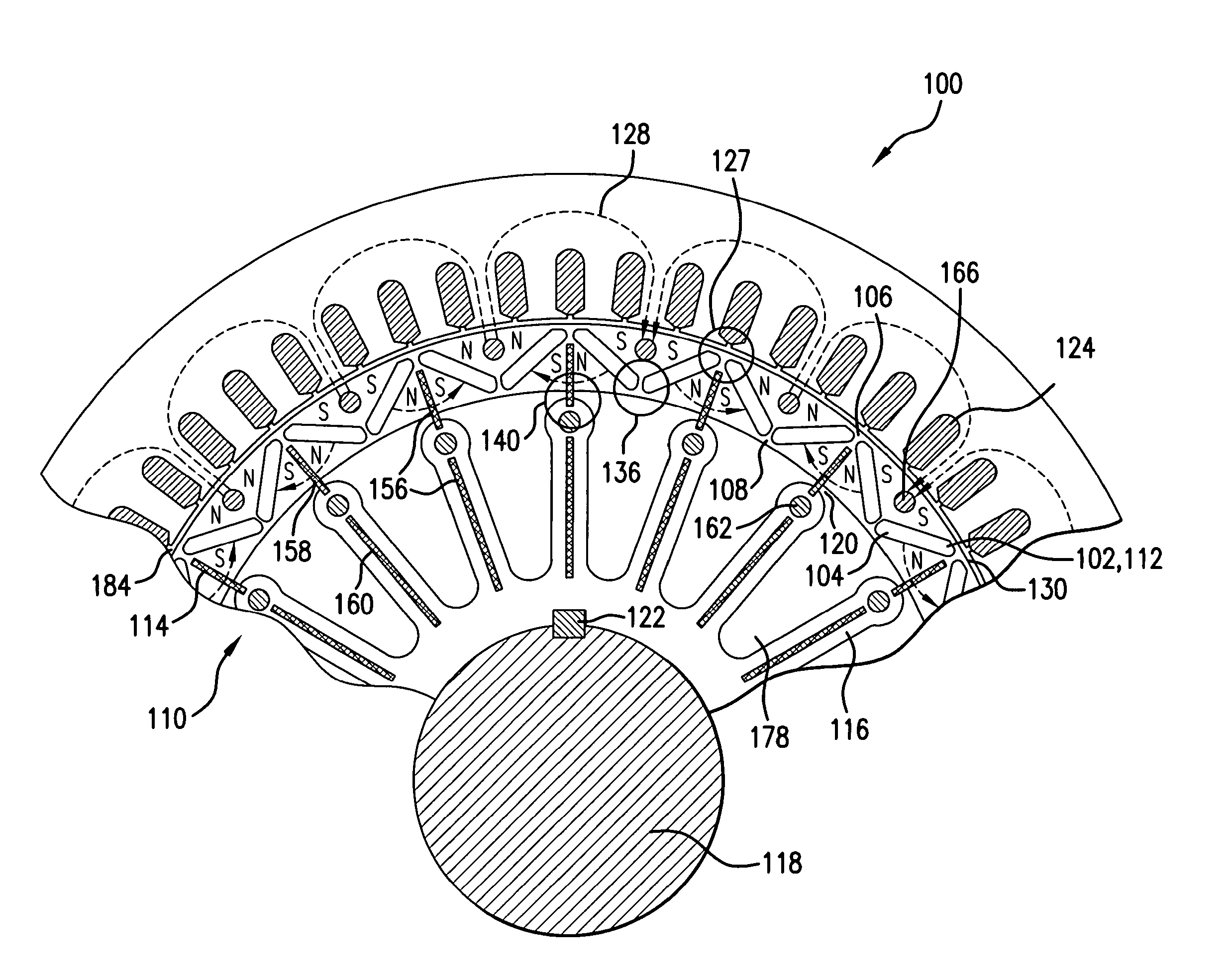
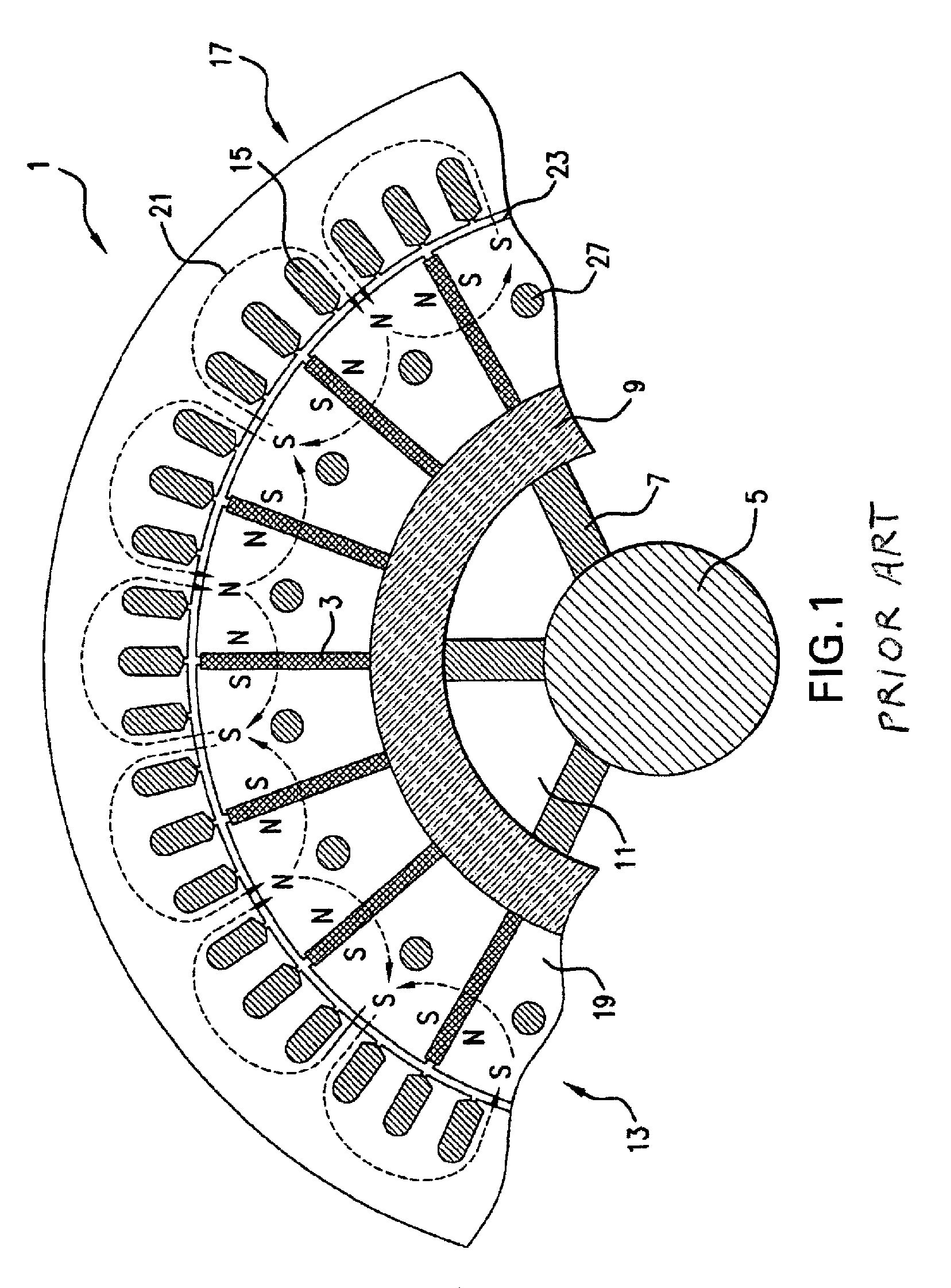
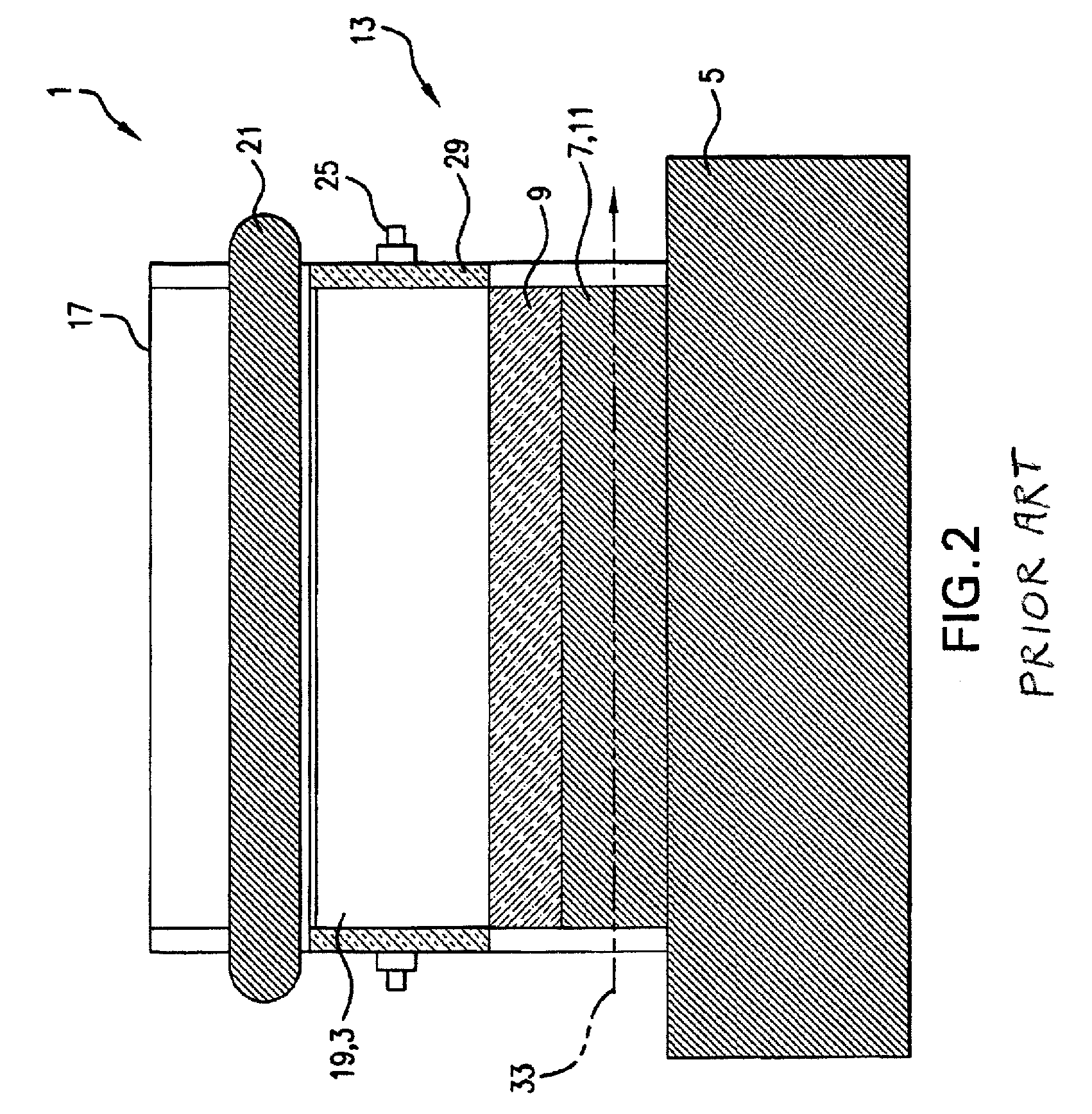
[0023]Conventional Focused Flux Magnet Mounting, Cooling and Assembly: FIG. 1 illustrates the conventional mounting 1 of focused flux mounted magnets 3. Mounted to the generator or motor shaft 5 through its struts 7 is a non-ferrous inner support ring 9, and between the struts 7 are a series of axial cooling vents 11 through which cooling air is blown through the generator. In a generator, the magnets 3 in the turning rotor 13 induce voltage and current in the windings 15 of the outer stator ...


PUM


Abstract

Permanent magnets are mounted within an electrical machine in a pitched saw-tooth pattern around the rotor shaft. This focused flux configuration provides for improved magnet mounting strength without resort to bonding or taping; provides improved rotor and stator cooling by access to the axial generator air flow; and provides for a simpler and more easily manufactured design. A laminated version of this basic structure provides for reduced surface losses and self-heating.

Description

BACKGROUND OF THE INVENTION[0001]1. Field of the Invention[0002]The present invention relates generally to devices and methods for assembling permanent magnet electrical machines, and more particularly to an apparatus and method for improving focused flux configured devices.[0003]2. General Background and State of the Art[0004]Permanent magnets make it reasonable to build electrical machines (defined here as motors and generators) using these for field generation rather than electro-magnets. Typically the magnets are mounted on an inner rotor, but outer rotor mounting is also used. In a generator, the rotation of the magnets on the rotor generates magnetic fields that induce voltages and currents in the windings of the radial outward stator. In a motor, the magnets react to voltages and currents applied to the stator and cause rotation of the rotor.[0005]Permanent magnet electrical machines are more compact and simpler and require less maintenance than their electromagnetic brethren...

Claims


Application Information

Patent Timeline
Patent Type & Authority Patents(United States)
IPC IPC(8): H02K1/22
CPCH02K1/2766H02K1/32H02K1/30
Inventor GOTTFRIED, CARLOS
Owner POTENCIA IND LLC
Learn More