Object specifying device for a vehicle

a technology for objects and vehicles, applied in vessel parts, steering initiations, instruments, etc., can solve the problems of forward vehicle obstructing the view of a manhole, high probability, and device cannot detect the manhol

Active Publication Date: 2012-07-03
DENSO CORP
View PDF5 Cites 1 Cited by
  • Summary
  • Abstract
  • Description
  • Claims
  • Application Information

AI Technical Summary

Benefits of technology

[0009]An object of the present invention is to provide, with due consideration to the drawbacks of the conventional object specifies device, an object specifying device of a controlled vehicle that reliably specifies an object, of which the view can be obstructed by a forward vehicle running at the forward area of the controlled vehicle, as a non-control-based object so as not to control the controlled vehicle on the basis of a movement of the non-control-based object.
[0010]Further, the object of the present invention is to provide a vehicle control apparatus which controls the controlled vehicle on the basis of a movement of a control-based object specified by the device, regardless of a movement of a non-control-based object specified by the device.

Problems solved by technology

However, during the running of the controlled vehicle and the forward vehicle on a straight road, the forward vehicle obstructs the view of a manhole placed on the road.
Therefore, the device cannot detect the manhole until the forward vehicle passes through on or over the manhole.
That is, there is a high probability that the device cannot detect the manhole until the manhole passes through the judging area of the forward vehicle.
In this case, the device cannot detect that the manhole has passed through the judging area of the forward vehicle.
As a result, there is a high probability that the device cannot specify the manhole as an unnecessary object.

Method used


Image

  • Object specifying device for a vehicle
  • Object specifying device for a vehicle
  • Object specifying device for a vehicle

Examples


embodiment

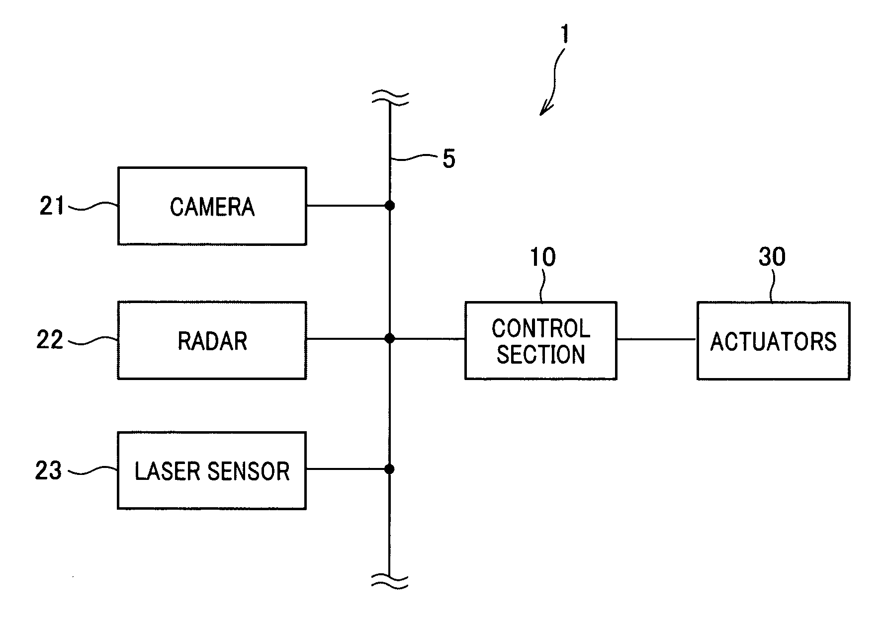
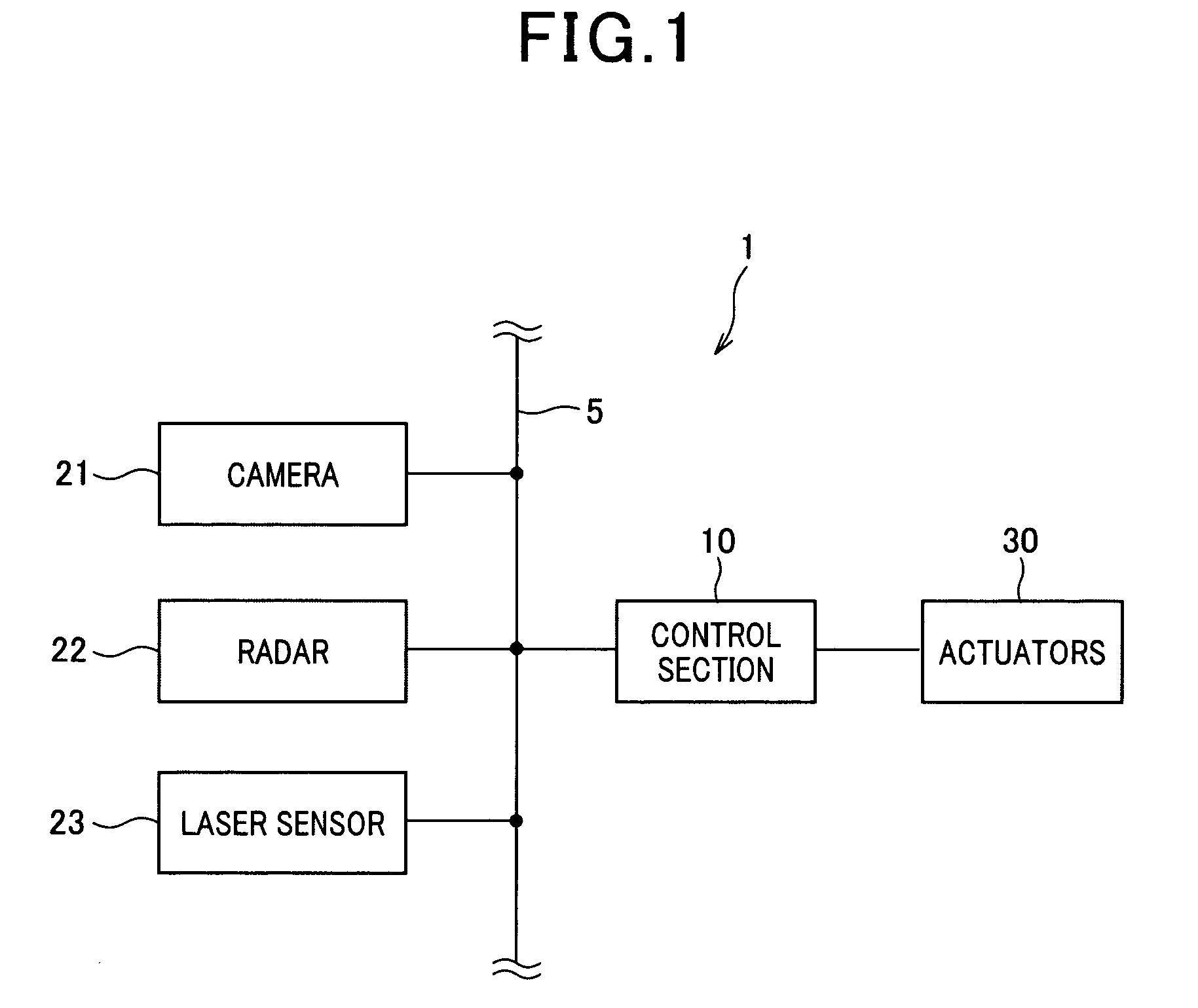
[0024]FIG. 1 is a block diagram of a vehicle control system according to the embodiment. A vehicle control system 1 is mounted in a vehicle (hereinafter, called a controlled vehicle) such as a passenger car or the like. As shown in FIG. 1, the system 1 has a camera 21, a radar 22, a laser sensor 23 and a control section 10 connected with one another through a communication line 5. The control section 10 acts as an object specifying device. The system 1 further has a plurality of actuators 30 acting as a vehicle control unit.

[0025]The camera 21 takes a photograph of a monitoring area set along the running direction of the vehicle and transmits the photographed picture to the control section 10. The radar 22 is formed of a well-known millimeter wave radar. This radar 22 radiates a beam of electromagnetic wave such as electric wave, light wave or the like set in the millimeter wave band to the monitoring area. This beam is reflected by each of a plurality of objects existing in the mon...


PUM


Abstract

An object specifying device mounted in a controlled vehicle has a unit for tracking objects, existing in a monitoring area set along a running direction of the controlled vehicle, to detect the objects as forward objects, a unit for specifying one forward object running in the area as a forward vehicle, a unit for specifying each of other forward objects as a candidate for a control-based object when the forward object is placed in an inter-vehicle area between the controlled and forward vehicles, and a unit for specifying each candidate, tracked for a tracking period equal to or longer than a reference tracking period, as a control-based object and specifies each candidate, tracked for a tracking period shorter than the reference tracking period, as a non-control-based object. The controlled vehicle is controlled according to a movement of the control-based objects, regardless of a movement of the non-control-based objects.

Description

CROSS-REFERENCE TO RELATED APPLICATION[0001]This application is based upon and claims the benefit of priority of the prior Japanese Patent Application 2009-162774 filed on Jul. 9, 2009, so that the contents of which are incorporated herein by reference.BACKGROUND OF THE INVENTION[0002]1. Field of the Invention[0003]The present invention relates to an object specifying device which specifies each of a plurality of objects existing in the forward area of a controlled vehicle as a control-based object when the vehicle should be controlled on the basis of the movement of the object and specifies each of the objects as an unnecessary object when it is not required to control the vehicle on the basis of the movement of the object. The present invention also relates to a vehicle control apparatus which controls the vehicle on the basis of movements of the control-based objects specified by the device while disregarding movements of the unnecessary objects specified by the device.[0004]2. D...

Claims


Application Information

Patent Timeline
Patent Type & Authority Patents(United States)
IPC IPC(8): G05D1/00G06F17/00B60R1/00B60W30/00B60W30/165G06T1/00G08G1/16
CPCB60W30/16
Inventor SAMUKAWA, YOSHIENOZAWA, TOYOHITO
Owner DENSO CORP
Why Eureka
Try Eureka