Pulse-width modulation control for backlighting of a video display

a backlighting and video display technology, applied in lighting devices, instruments, light sources, etc., can solve the problems of high pulse-width modulation backlight control current pulse rate, unfavorable synchronization of both rates using a common clock source, motion artifacts, etc., to minimize or eliminate perceptible flicker, mitigate flicker effect, and minimize the effect of flicker

Active Publication Date: 2012-07-10
APPLE INC
View PDF9 Cites 2 Cited by
  • Summary
  • Abstract
  • Description
  • Claims
  • Application Information

AI Technical Summary

Benefits of technology

[0011]In accordance with the present invention, in a pulse-width modulated backlight control for a video display, the pulse-width modulated backlight control current pulse train is resynched to the video refresh rate on occurrence of a video refresh pulse. In order to prevent an undesirable momentary increase in brightness, or flicker, in the event that the pulse train is restarted soon after a pulse has occurred relative to the normal pulse interval, this resynchronization does not result in immediate restart of the pulse-width modulated backlight control current pulse train at full pulse width. Instead, the width, and possibly the timing, of the first backlight control current pulse after resynchronization are adjusted so that the duty cycle remains constant, to avoid any perceptible flicker.
[0012]In one embodiment, the first backlight control current pulse after resynchronization occurs essentially on occurrence of the video refresh pulse, so that it is closer to the previous backlight control current pulse than a normal pulse-width modulation pulse interval. In this embodiment, to mitigate the flicker effect of having the first backlight control current pulse after resynchronization closer than normal to the previous pulse, the width of the first backlight control current pulse after resynchronization is reduced from a first value determined by the desired brightness to a second value that bears the same proportion to the first value that the interval between the beginning of the previous backlight control current pulse and the beginning of the first backlight control current pulse bears to the normal pulse interval. Thus, the average duty cycle, over the combination of the shortened pulse interval before the video refresh pulse and the first pulse interval after the video refresh pulse, is constant, minimizing or eliminating perceptible flicker.
[0013]In a second embodiment, the first backlight control current pulse after resynchronization still occurs one pulse-width modulation pulse interval after the rising edge of the previous backlight control current pulse, while the second backlight control current pulse after resynchronization occurs one pulse-width modulation pulse interval after the rising edge of the video refresh pulse. To mitigate the flicker effect from having those first and second pulses closer together than one pulse-width modulation pulse interval, the width of the first backlight control current pulse may be reduced from a first value determined by the desired brightness to a second value that bears the same proportion to the first value that the interval between the beginning of the first backlight control current pulse and the beginning of the second backlight control current pulse bears to the normal pulse interval. In that way, the duty cycle during the shortened pulse interval is the same as that during a normal pulse interval, and there is no perceptible increase in backlight brightness.

Problems solved by technology

However, in many types of solid-state video displays, the elements that display the video data do not generate their own light, and must be coupled with a separate light source.
This complete lack of a fixed-phase relationship between the two signals may result in motion artifacts (e.g., a “waterfall” effect) in the video display when the refresh pulses do not coincide with the pulse-width modulated current pulses, for which there may be a number of solutions.
However, the video subsystem and the backlight subsystem are typically completely separate, so that synchronizing both rates using a common clock source is not practical or desirable, and very high pulse-width modulated backlight control current pulse rates also are not desirable.
The occurrence of two current pulses close together may cause a noticeable, if momentary, brightness increase or “flicker,” which also is undesirable.

Method used


Image

  • Pulse-width modulation control for backlighting of a video display
  • Pulse-width modulation control for backlighting of a video display
  • Pulse-width modulation control for backlighting of a video display

Examples


Embodiment Construction

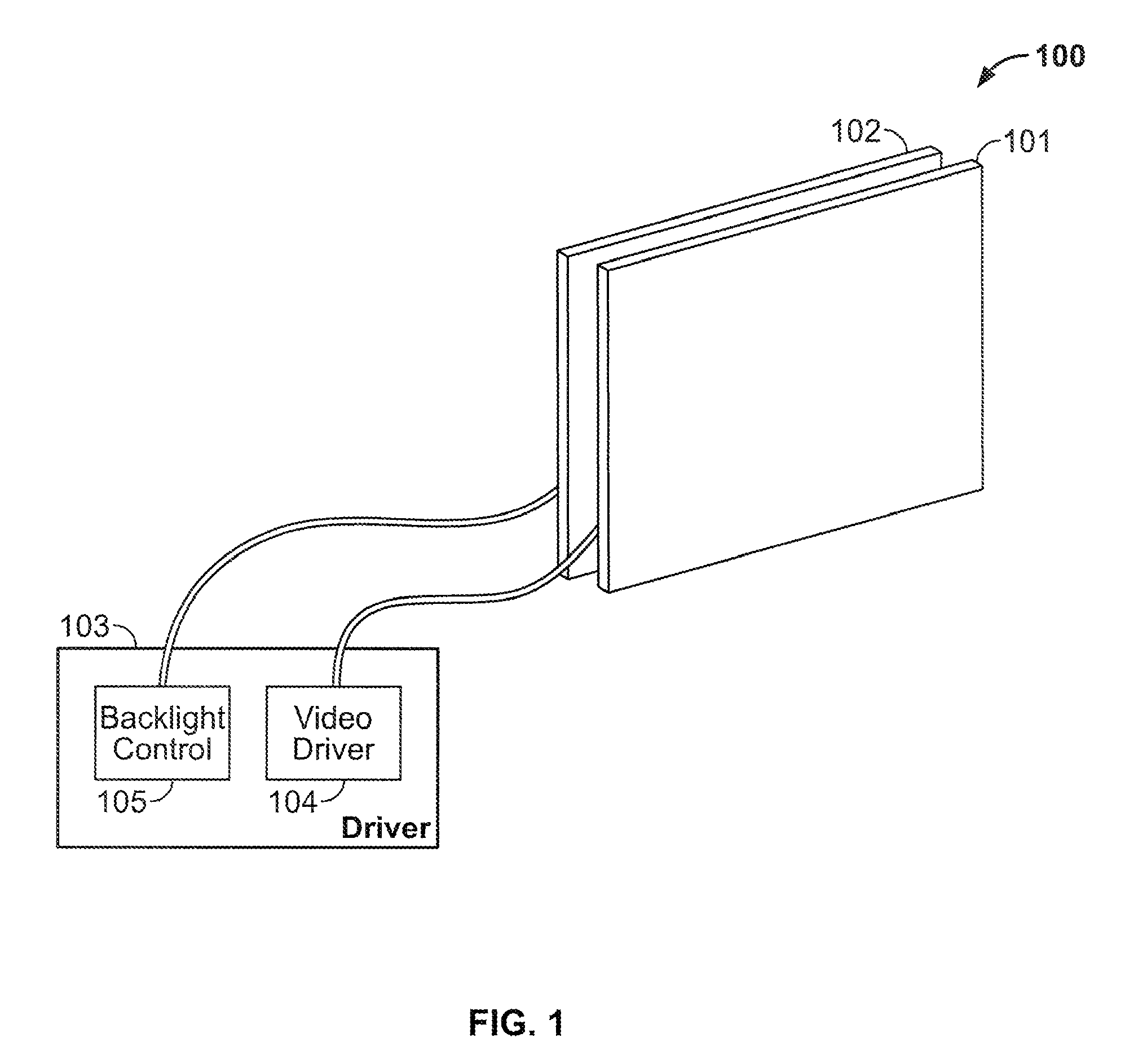
[0024]FIG. 1 shows, schematically, a video display 100 of the type with which the present invention may be used. Video display 100 includes a video array 101 which may be, e.g., a liquid crystal array as described above, and a backlighting source 102. Although backlighting source 102 is shown as having an area coextensive with that of video array 101, the actual light source of backlighting source 102 may occupy a small area, and its output may be spread over video array 101 using appropriate reflectors, light pipes, etc. (not shown).

[0025]Driver circuitry 103 may include a video driver 104 that drives video array 101, and a separate backlight control 105 for backlighting source 102.

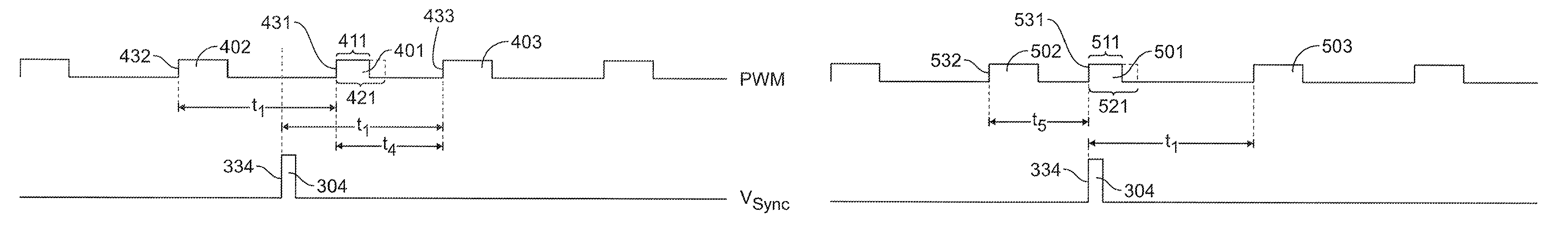
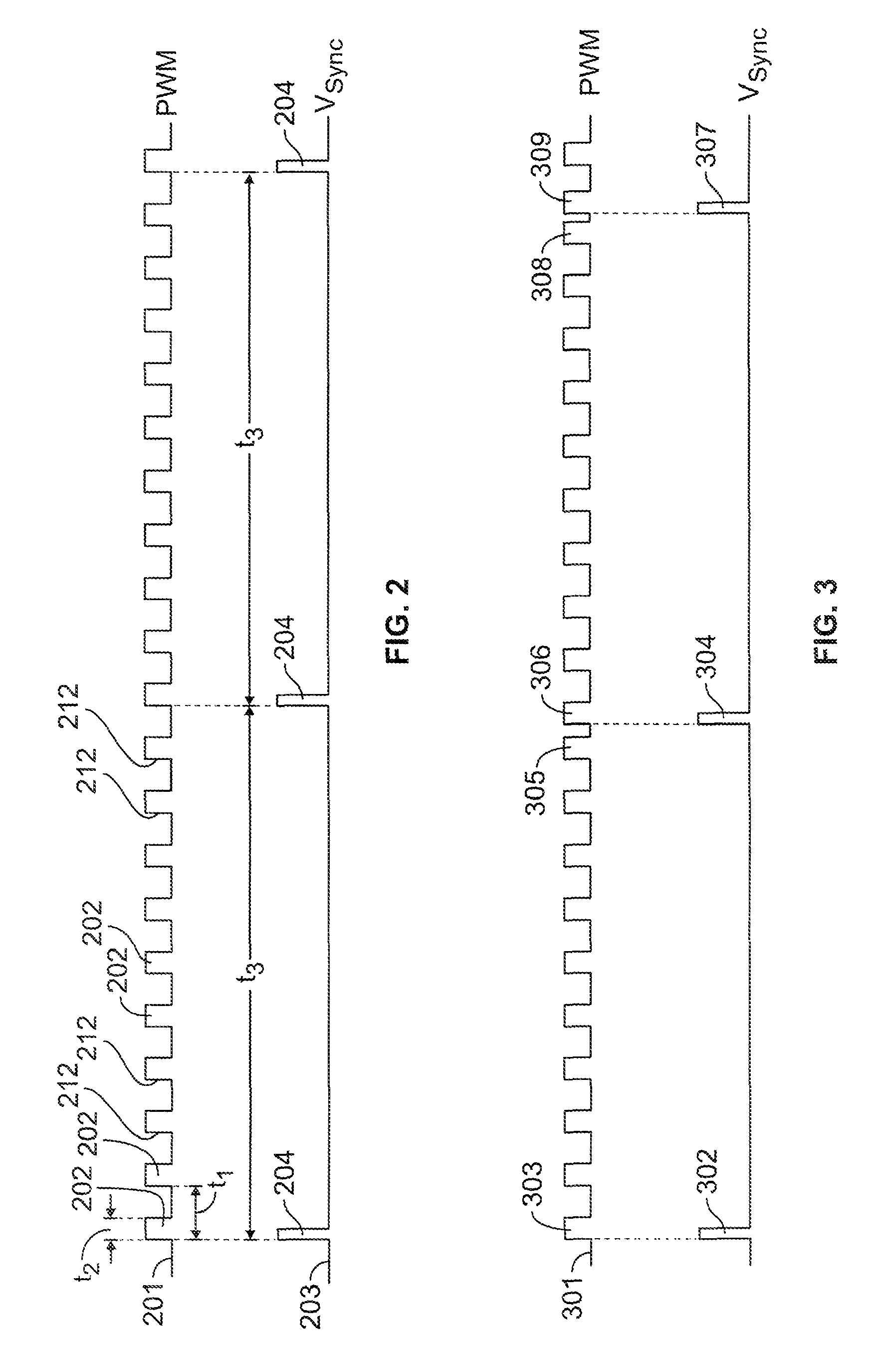
[0026]FIG. 2 shows a train 201 of pulse-width modulated current pulses 202 for controlling backlighting unit 102. The pulse interval t1 is the duration between the rising edges 212 of adjacent pulses 202. The brightness of backlighting source 102 may be determined by the duty cycle of pulse train 201—i.e...


PUM


Abstract

A pulse-width modulated backlight control for a video display restarts the pulse-width modulated pulse train on occurrence of a video refresh pulse. In order to prevent an undesirable momentary increase in brightness in the event that the last pulse of the pre-refresh pulse train occurs too close to the first pulse of the post-refresh pulse train relative to the normal pulse interval, the width of the first pulse following refresh may be reduced from a first value determined by the desired brightness to a second value that bears the same proportion to the first value that the interval between the beginning of the previous pulse and the occurrence of the refresh pulse bore to the normal pulse interval. In that way, the duty cycle during the shortened pulse interval is the same as during a normal pulse interval, avoiding or minimizing perceptible increase in backlight brightness.

Description

CROSS REFERENCE TO RELATED APPLICATION[0001]This claims the benefit of commonly-assigned U.S. Provisional Patent Application No. 61 / 113,141, filed Nov. 10, 2008, which is hereby incorporated by reference herein in its entirety.BACKGROUND OF THE INVENTION[0002]This invention relates to controlling the backlighting of a video display. In particular, this invention relates to control of backlighting separately from the video display itself without introducing visual artifacts in the display.[0003]In early video displays based on cathode-ray tube technology, the display generated its own light. However, in many types of solid-state video displays, the elements that display the video data do not generate their own light, and must be coupled with a separate light source. For example, liquid crystal displays operate by selectively lightening and darkening elements in an array, allowing light to shine through from behind the array. In such displays, the light source is generally a backlight...

Claims


Application Information

Patent Timeline
Patent Type & Authority Patents(United States)
IPC IPC(8): G09G3/36
CPCG09G3/3406H05B33/0818H05B33/086G09G2320/0247G09G2320/0261G09G2320/064Y02B20/346H05B47/10Y02B20/30
Inventor BARNHOEFER, ULRICHYAO, WEIKIM, TAESUNG
Owner APPLE INC
Why Eureka
Try Eureka