
Above-water monitoring of swimming pools

a technology for monitoring and swimming pools, applied in burglar alarms, television systems, instruments, etc., can solve the problems of reducing the accuracy of alarms, requiring extensive or cumbersome calibration methods or algorithms, and limiting the functionality of above-described prior-art devices. , to achieve the effect of improving reliability and reducing costs

Active Publication Date: 2012-08-07
DAVID B & ANN E ANDERSON REVOCABLE TRUST
View PDF13 Cites 37 Cited by
  • Summary
  • Abstract
  • Description
  • Claims
  • Application Information

AI Technical Summary

Benefits of technology

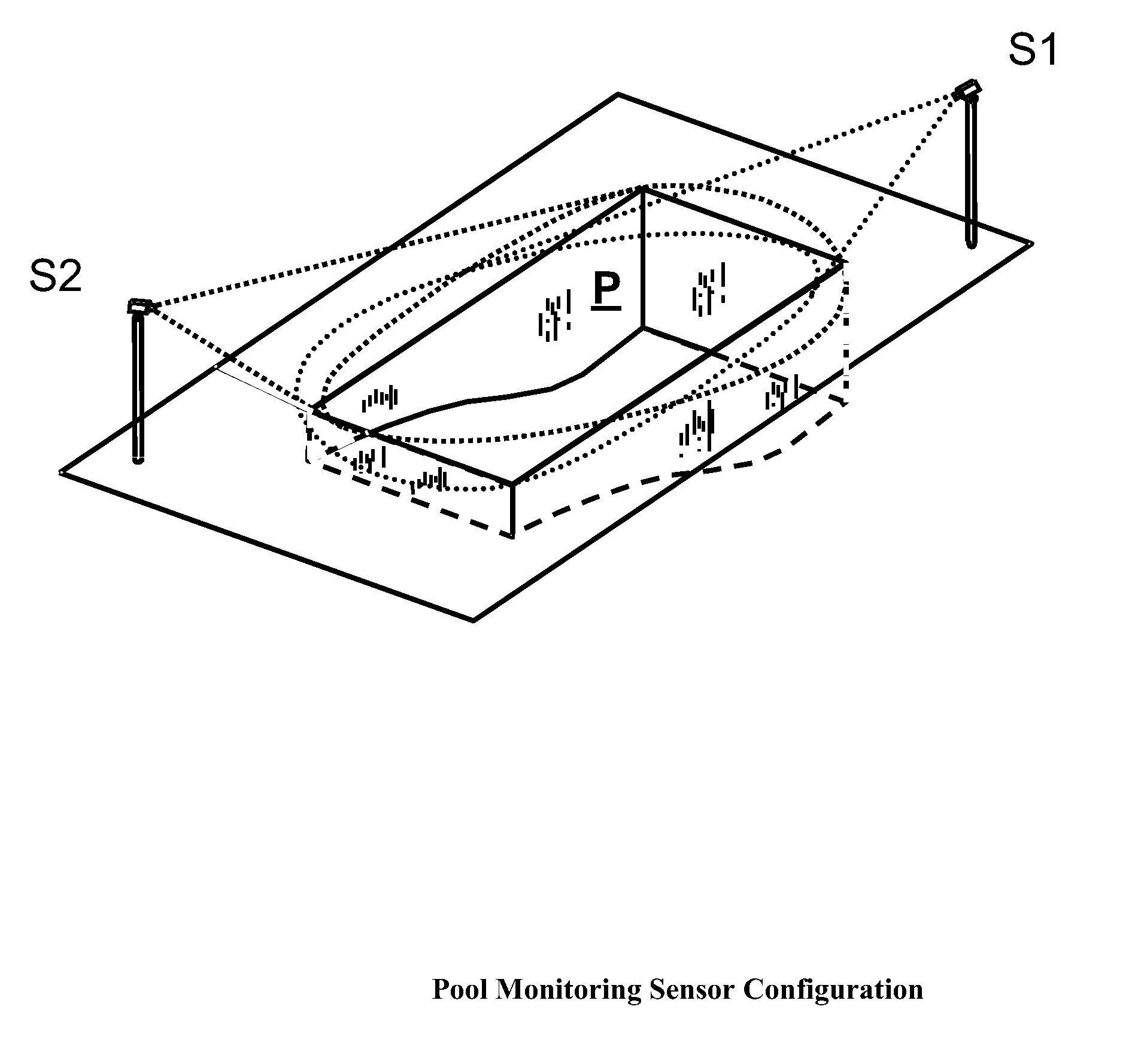
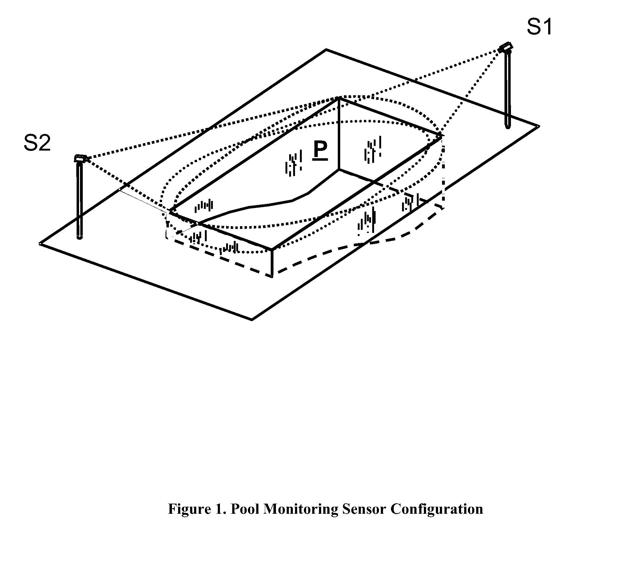
[0015]The present invention uses passive ranging techniques to estimate the three-dimensional location of objects on or under the surface of the pool. Further, the invention uses spectral processing to account for variations in lighting and water quality conditions, and uses spatial processing to untangle the distortions introduced by the roughened water surfaces. Finally, the present invention employs one or more polarizing lenses and / or special spectral filters to overcome glare, shadows and the like.
[0016]Together, the above-described procedures overcome the limitations which have prevented devices of the prior art from being moved from below the water line to a position above the pool. The present invention overcomes the effects of surface distortions to reconstruct an undistorted view of underwater swimmers.
[0020]In addition to the above, the system is programmed to compare sequential images to determine which pixels, if any, are artifacts due to glint. Such pixels can be discarded to improve the quality of the images.
[0024]The invention has the further object of reducing the cost, and improving the reliability, of systems and methods for monitoring pools for possible drowning victims.

Problems solved by technology

The above-described prior-art devices are limited in their functionality, in that all require the mounting of sensors below the surface of the water.
Mounting the sensors below the surface requires a more costly and disruptive installation procedure, requiring the routing of power and data wires underwater, or through the pool walls, back to the sensor processing hardware.
Also, the systems of the prior art require extensive or cumbersome calibration methods or algorithms to reduce false alarm rates.
However, the use of such a system involves the cost and complications of draining the pool, drilling large holes into the pool wall, installing watertight video camera housings, and excavating behind the wall to route wires to the cameras.
Moreover, in the above-described system, because the underwater cameras must be flush with the wall contours, the system has blind spots immediately adjacent to the pool walls, especially near the cameras.
The prior art system must accept these disadvantages as the price for avoiding the additional signal processing needed to extract useful images if the cameras were mounted above the water surface.
Pool-mounted active sensors are likely to be accidentally dislodged or blocked by swimmers, thus disabling one or more of the sensors.
As in the above-described patent, its sensors are vulnerable to accidental dislodgment and / or blockage by swimmers.
The sonar systems of the prior art could not be mounted above the water surface.
However, the prior art has taught against doing so, because of the intractable problems encountered.
Specifically, the air-water boundary presents a number of challenges to sensing algorithms and makes it impractical simply to move an underwater system to a position above the water line.
Objects appear disjointed to an observer and often are missing segments due to changes in surface refraction distorting and breaking up the sensed image of underwater objects.
Moreover, varying water quality and lighting conditions alter the sensed image of the water being monitored, adding to the difficulty of using above-pool sensors.
For these reasons, it is impractical simply to move an underwater system of the prior art to a position above the water line.

Method used


Image

  • Above-water monitoring of swimming pools
  • Above-water monitoring of swimming pools
  • Above-water monitoring of swimming pools

Examples


Embodiment Construction

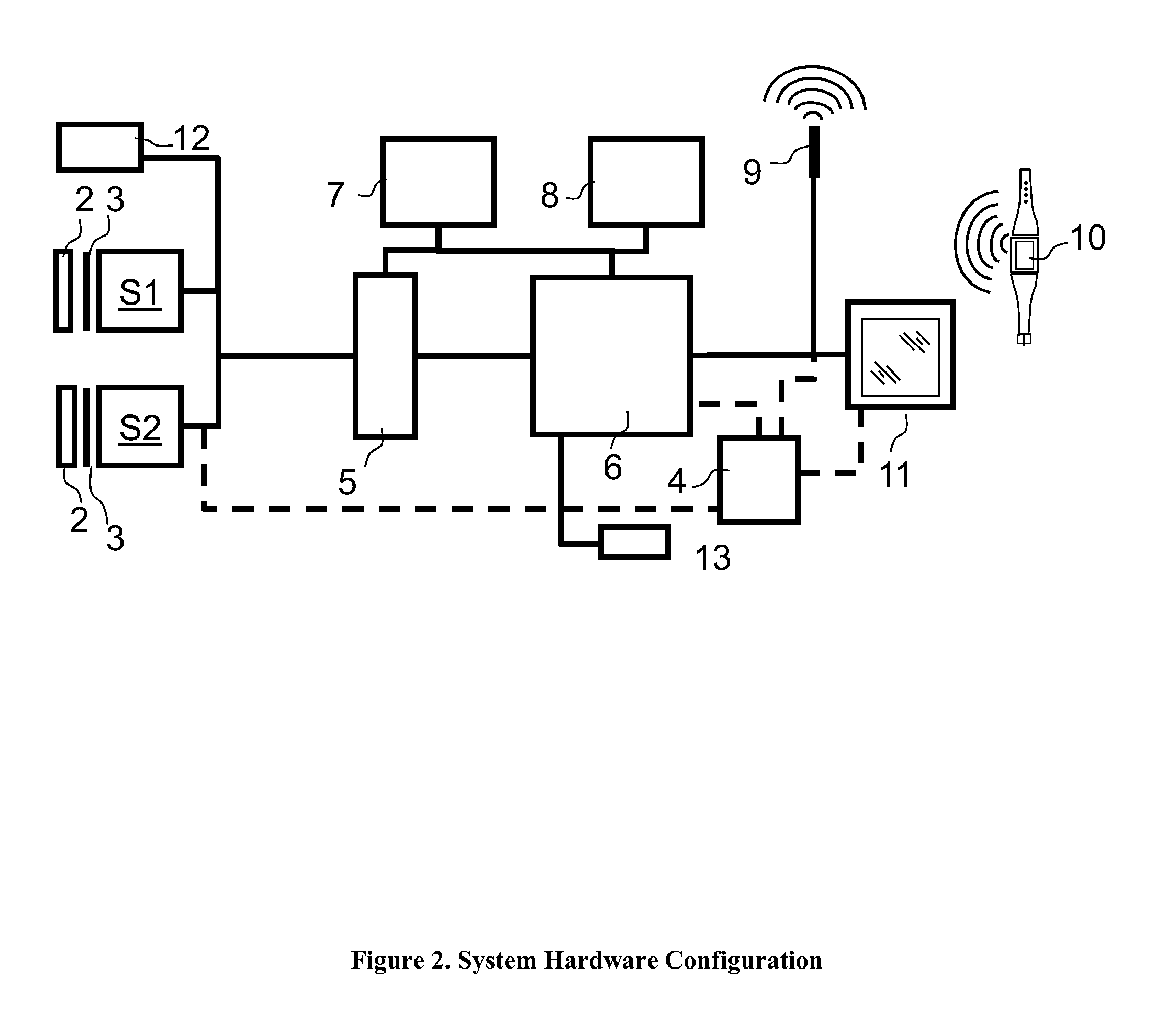
[0032]In the following description of an above-water system for monitoring pools for possible drowning victims, reference is made to the accompanying drawings forming a part thereof. These drawings show by way of illustration, a specific embodiment in which the invention may be implemented. Other embodiments may be utilized and structural changes may be made without departing from the scope of the present invention.

[0033]In this specification, the term “video” is defined as a series of time sequenced electro-optical (EO) images within a portion of the bandwidth of wavelengths from infra-red to ultraviolet energy. The EO sensors may be mounted on rigid poles, walls, or ceilings, or any combination thereof. The sensors receive video images of the pool surface including images of humans and objects within the water volume, at or below the surface.

[0034]The EO sensor housing may include a pair of apertures at a known separation distance providing stereoscopic images of the field of view...


PUM


Abstract

An above-water system provides automatic alerting for possible drowning victims in swimming pools or the like. One or more electro-optical sensors are placed above the pool surface. Sequences of images are digitized and analyzed electronically to determine whether there are humans within the image, and whether such humans are moving in a manner that would suggest drowning. Effects due to glint, refraction, and variations in light, are offset automatically by the system. If a potential drowning incident is detected, the system produces an alarm sound, and / or a warning display, so that an operator can determine whether action must be taken.

Description

CROSS-REFERENCE TO PRIOR APPLICATION[0001]Priority is claimed from U.S. provisional patent application Ser. No. 61 / 084,078, filed Jul. 28, 2008, entitled “Above-water System for Alerting of Possible Drowning Victims in Pools of Water”, the entire disclosure of which is incorporated by reference herein.BACKGROUND OF THE INVENTION[0002]The present invention relates generally to the field of automated monitoring of swimming pools, and the like, to detect possible drowning victims. More specifically, the invention relates to systems which use only sensors that are above the water line, to alert responsible persons monitoring a pool of water, by detecting behaviors consistent with those of someone who is unconscious or otherwise incapacitated.[0003]Devices for automated monitoring of swimming pools have been known in the prior art. Such devices have employed video or other sensor technologies, such as sonar. Examples of such devices are given in U.S. Pat. Nos. 6,133,838, 7,330,123, and 5...

Claims


Application Information

Patent Timeline
Patent Type & Authority Patents(United States)
IPC IPC(8): G08B23/00
CPCG08B21/086
Inventor ANDERSON, DAVID BRADFORDBARNETT, JOHN THOMASHAKES, DONALD LEELOSS, KEITH ROGERGORMICAN, JAMES PAUL
Owner DAVID B & ANN E ANDERSON REVOCABLE TRUST
Learn More