
Three-wheeled motorcycle

a three-wheeled motorcycle technology, applied in the direction of vehicle components, pedestrian/occupant safety arrangements, understructures, etc., can solve the problems of trikes, in general, dangerous even to the most experienced drivers, flipping or turning, etc., to reduce the risk of tipping or overturning

Inactive Publication Date: 2011-02-17
ACKLEY RAYMOND
View PDF18 Cites 13 Cited by
  • Summary
  • Abstract
  • Description
  • Claims
  • Application Information

AI Technical Summary

Benefits of technology

[0012]An object of the present invention is to provide a three-wheel motor vehicle which is powered from two rear wheels mounted on a primary support frame connected to a single steerable front wheel with a low center of gravity in order to reduce tipping or overturning of the three-wheel motor vehicle, Known as a trike.
[0013]Another object of the present invention is to provide an improved three-wheel motor vehicle having outstanding safety characteristics and overall operating efficiency.
[0014]Another object of the present invention is to provide an aerodynamically designed three-wheel motor vehicle with a low center of gravity to overcome the effects of centrifugal force when the vehicle is going into and through a turn at normal and high speeds so as to maneuver the turn with complete safety and at speeds much higher than would normally be safe.

Problems solved by technology

A common problem with known three-wheel motorcycles, known as “trikes”, is their vulnerability to flipping or turning over upon entering and / or maneuvering through a turn at high speeds, or even at more moderate speeds.
This tendency to turn or flip over makes trikes, in general, dangerous even to the most experience drivers.
The problem of flipping or turning over is created by centrifugal force acting upon the relatively high center of gravity of the vehicle of the existing trikes.
However, with three-wheel vehicles this normally cannot be done because of the action of three wheels instead of two.
Thus, one major problem that exists today with trikes is there to flip or turnover when maneuvering turns even at normal speeds.
Another problem with known devices that do permit the banking or tilting of the operator and / or passengers is that a good portion or even most of the weight of the vehicle itself does not tilt which only partially solves the problem.
The engine of the vehicle is one of the heaviest components overall and failure to mount the power plant so that it may bank is one of the limitations of these known devices.
Again the problem in these vehicles is due to the relatively high center of gravity.
A trike having a design that allows the rifer to tilt the trike so as to achieve a better center of gravity requires skill and total concentration at all times. A single distraction and failure to tilt the trike enough could cause the trike to tip or turnover with disastrous results.
Yet still another problem of known devices, which employ mechanism for banking or tilting portions of the vehicle, is that they do not provide fail-safe mechanism for the operating structure thereof.
This could cause the trike to crash if tilting of the trike is not brought to the proper position after the turn is completed.
Again, even riders with the most skill can misjudge a turn and tip or overturn.
Still yet another problem that exist with trikes available today is that the designs available have a tremendous wind resistance and drag thereby making them less fuel efficient than can be expected from a vehicle with the weight-to-power ratio.
Another problem with existing trike is the comfort level of the rider and passenger during riding.
This position not only places most of the weight on the butt thereby leading to back strain, but also impedes bloods flow to the lower extremities.
Still yet another problem with the existing tikes is there lack of storage room.
This not only makes the trike unstable, but it also increases fuel consumption due to one or more additional wheels being on the road.
These problems together with many others such as difficulty in cooling internal combustion operated engines, the structural mounting of said engines, the problem of shock absorbing structures together with the lack of an automatic or semi-automatic operation all make existing tikes undesirable for average user.

Method used


Image

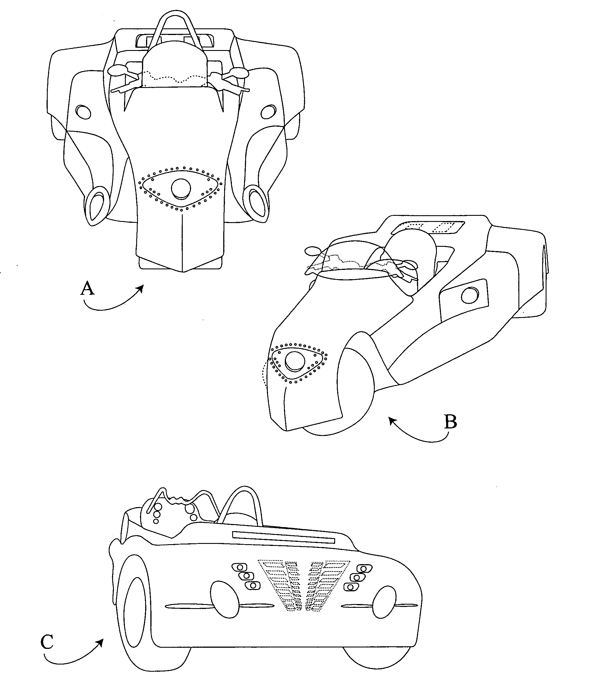
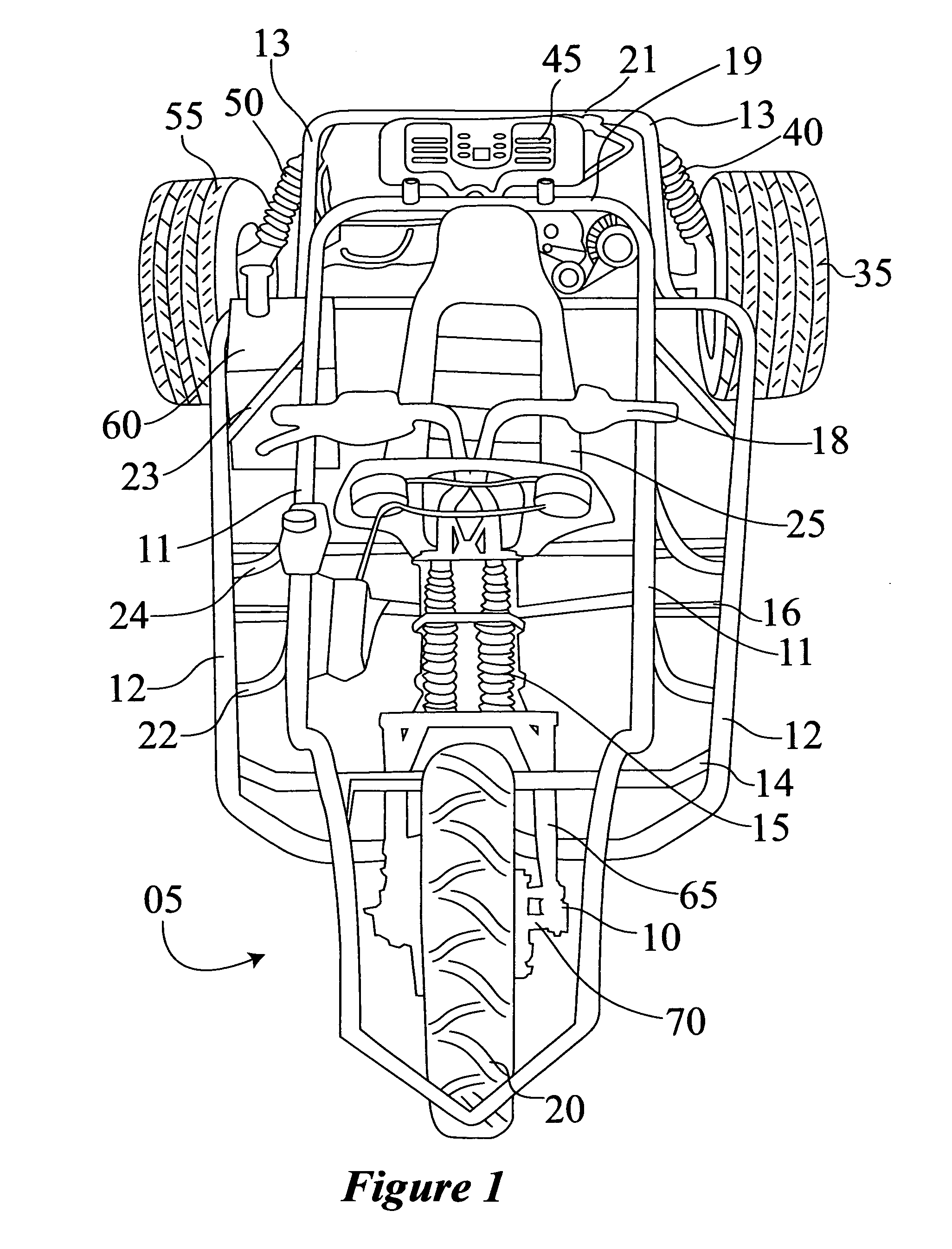
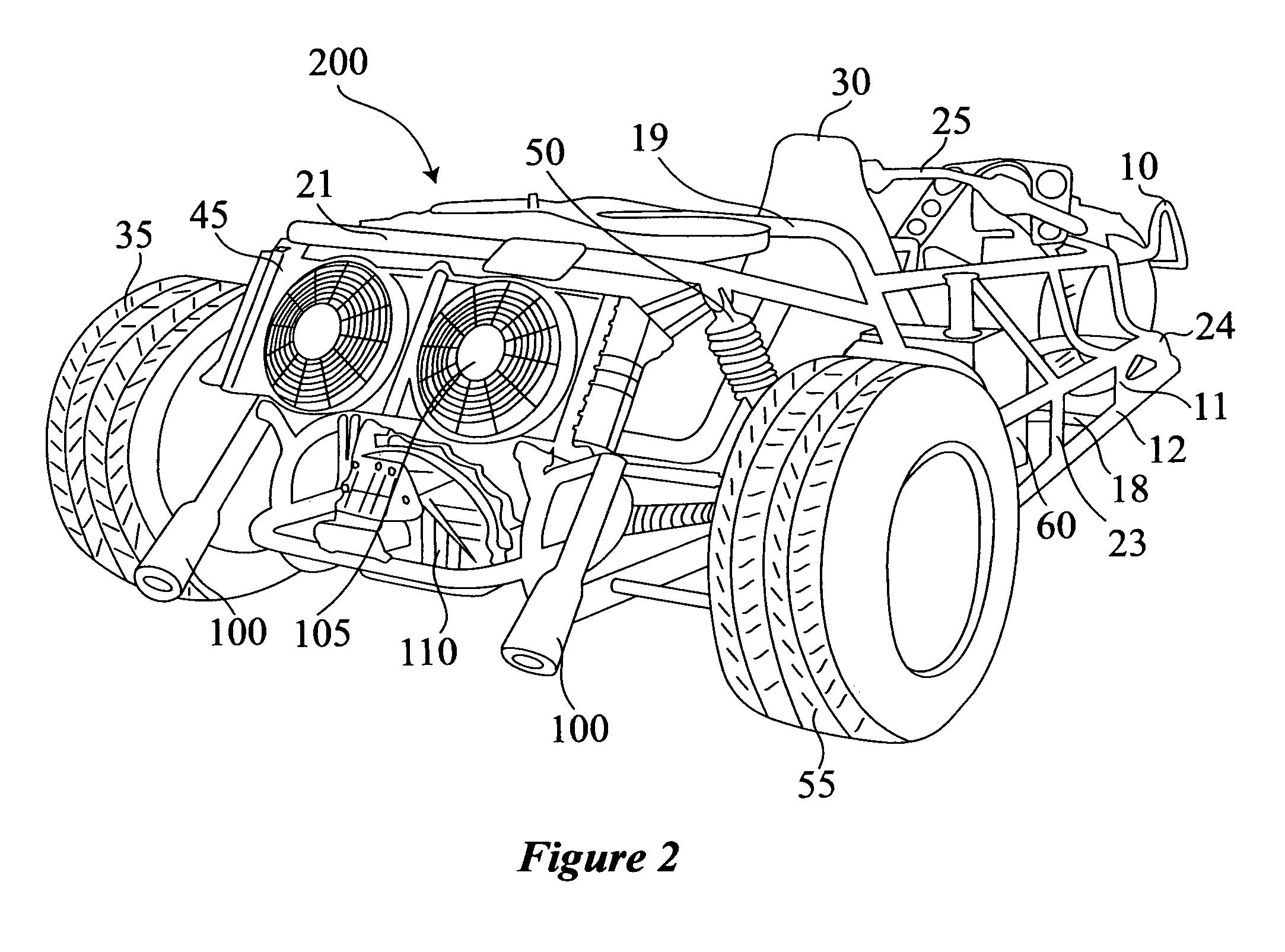
  • Three-wheeled motorcycle
  • Three-wheeled motorcycle
  • Three-wheeled motorcycle

Examples


Embodiment Construction

[0027]The present invention is directed to a stable, fuel-efficient three-wheeled motorcycle having a very low center of gravity, a sturdy frame, ample storage room, and excellent maneuverability.

[0028]The wheeled motorcycle of the present invention contains a metal frame that fully encases the driver and one passenger depending on the model that is being discussed. The tubular frame can be made from an extremely strong steel frame, namely 3140-chrome molly carbon steel. Although expensive, this steel has the tensile strength of about 90,000 pounds per square inch. This type of steel is used in high-speed racecars and is known for its strength and lightweight. Although this is the preferred type of material to be used other types of steel, metals, alloys, composite materials, man-made materials and combinations thereof can also be used.

[0029]The frame can be made from a single cast / mold or can be made out of separate pieces that are welded together. Should the frame be welded togeth...


PUM


Abstract

A three-wheel motorcycle having a support frame with rear wheels mounted on a double axle with differential there between for a drive from a powerful automobile type engine. A front portion of the frame supporting the front motorcycle type single steerable wheel and handlebars mounted thereto for conventional steering. Other features include a unique shock and spring mechanism for the support frame measuring no more than 6 inches off of the ground and having a center of gravity of 14 inches or less powered by an internal combustion engine.

Description

CROSS-REFERENCE TO RELATED APPLICATION[0001]This application is a non-provisional application and claims benefit to provisional application having the Ser. No. 61 / 273,865 filed Aug. 10, 2009, the disclosure of which is incorporated herein by reference in is entirety.FIELD OF THE INVENTION[0002]This invention relates generally to motorcycle-type devices having three wheels having high and reliable performance, maneuverability, usability, safety, gas mileage as a passenger-type vehicle as well as a sleek aerodynamic design.BACKGROUND OF THE INVENTION[0003]A common problem with known three-wheel motorcycles, known as “trikes”, is their vulnerability to flipping or turning over upon entering and / or maneuvering through a turn at high speeds, or even at more moderate speeds. This tendency to turn or flip over makes trikes, in general, dangerous even to the most experience drivers. The problem of flipping or turning over is created by centrifugal force acting upon the relatively high cente...

Claims


Application Information

Patent Timeline
IPC IPC(8): B62D61/08B60R21/20B60R21/18
CPCB62K5/027
Inventor ACKLEY, RAYMOND
Owner ACKLEY RAYMOND
Learn More