Material conveyor system container

a conveyor system and material technology, applied in the direction of mechanical machines/dredgers, soil shifting machines/dredgers, transportation and packaging, etc., can solve the problems affecting the operation of material transportation, and increasing the thickness of the material uniformly throughout the bucket structure. , to achieve the effect of reducing the capacity of the buck

Active Publication Date: 2012-08-14
MAXI LIFT INC
View PDF32 Cites 28 Cited by
  • Summary
  • Abstract
  • Description
  • Claims
  • Application Information

AI Technical Summary

Benefits of technology

[0005]In accordance with one important aspect of the invention, an elevator bucket is provided which has a thickened front wall and lip portion generally disposed at the point of insertion of the bucket into the material being conveyed by the bucket. In accordance with another aspect of the invention, an elevator bucket is provided which has sidewalls and, particularly, arcuate corner parts joining the sidewalls to a front wall or lip and which are provided of thickened material of which the bucket is made. The increased wall and corner part thickness is graduated from the leading edge of the front wall or lip of the bucket through the remainder of the front or bottom wall, the sidewalls and through the extent of the arcuate integral corner parts joining the sidewalls to the front or bottom wall.

Problems solved by technology

A longstanding problem with elevator buckets relates to excessive wear on the buckets incurred as they enter the flow of material being conveyed to scoop up or fill the buckets while they pass along their path of movement.
Premature failure and loss of bucket capacity can, of course, adversely effect material transport operations.
Increasing material thickness uniformly throughout the bucket structure is disadvantageous from the standpoint of cost and the added tare weight of the buckets, for example.

Method used


Image

  • Material conveyor system container
  • Material conveyor system container
  • Material conveyor system container

Examples


Embodiment Construction

[0013]In the description which follows, like parts are marked throughout the specification and drawings with the same reference numerals, respectively. The drawing figures may not necessarily be to scale and certain features may be shown in somewhat schematic form in the interest of clarity and conciseness.

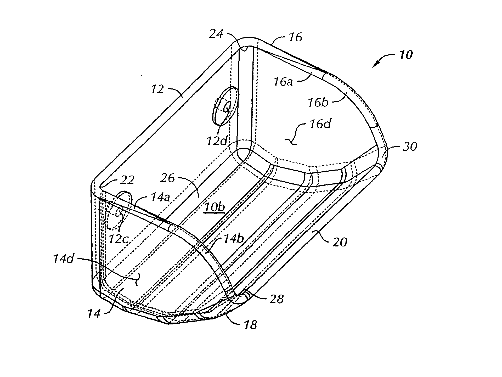
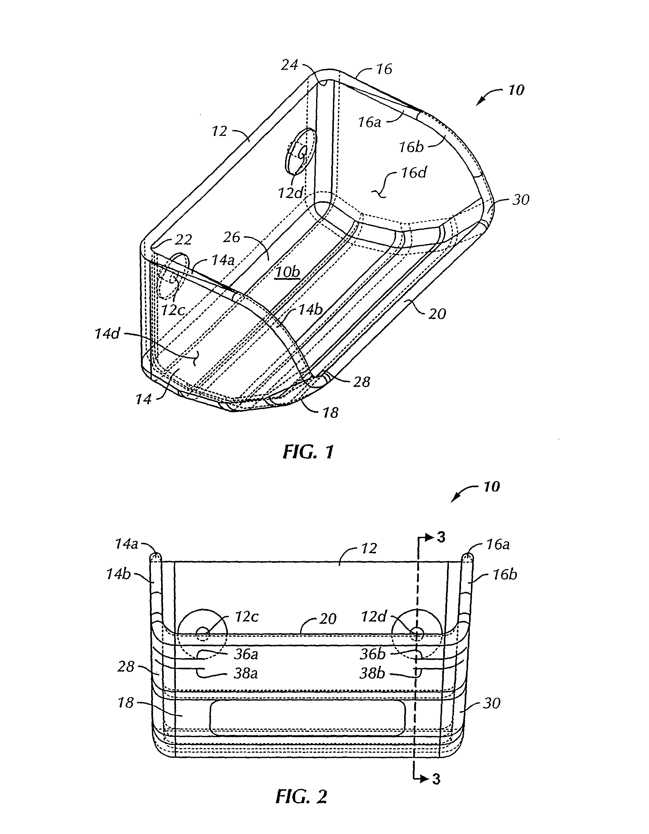
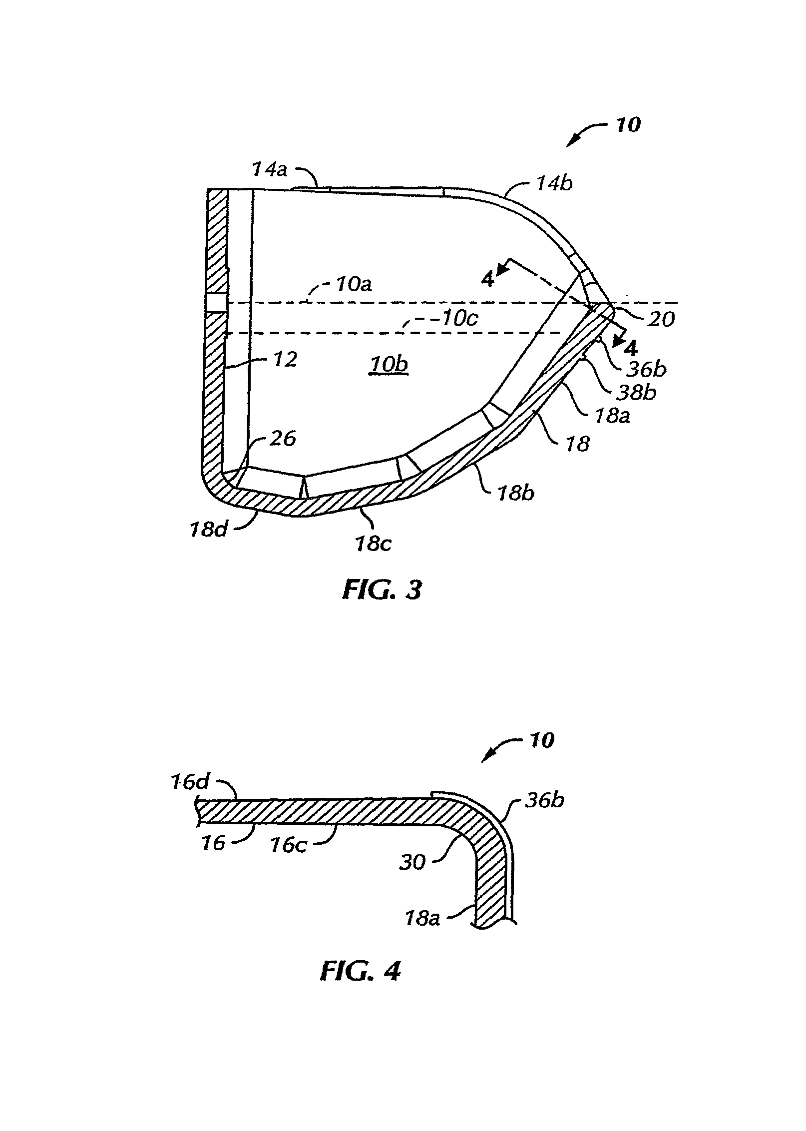
[0014]Referring to FIG. 1, there is illustrated an elevator bucket in accordance with the invention and generally designated by the numeral 10. The bucket 10 is characterized by a backwall 12, opposed sidewalls 14 and 16 and a combined front and bottom wall 18 delimited by a lip 20. Backwall 12 and sidewalls 14 and 16 are joined by integral arcuate corner parts 22 and 24, backwall 12 is joined to combined bottom and front wall 18 by an arcuate corner part 26 and combined bottom and front wall 18 is joined to sidewalls 14 and 16 by integral arcuate corner parts 28 and 30. The solid and dashed lines at the corner parts and arcuate edges denote points of tangency of the arcuate corne...


PUM


Abstract

Molded polymer elevator buckets are reinforced by tapering the thickness of front and sidewalls and integral arcuate corner parts to improve bucket life without significant weight increase or reduced bucket capacity. Front lip wear indicators may be molded into the front wall section delimited by the lip and / or on the arcuate corner parts.

Description

CROSS REFERENCE TO RELATED APPLICATION[0001]This application is a continuation of co-pending application Ser. No. 11 / 646,899, filed Dec. 28, 2006, which is a continuation of Ser. No. 11 / 522,750 filed Sep. 18, 2006.BACKGROUND OF THE INVENTION[0002]In the art of elevator-type material conveyor systems, containers or so-called “buckets” are supported spaced-apart on an endless belt or chain-like conveyor for moving particulate material substantially vertically at least between a first elevation and a second and higher elevation. A common application for elevator-type conveyor systems and the buckets associated therewith is for grain elevators as well as other applications wherein granular or particulate solid materials or material mixtures are conveyed by immersing the buckets in the material as the buckets move along the path of the endless belt or chain support structure. Heretofore, suitable materials for use in elevator buckets comprise polymers such as polyethylene, polyurethane a...

Claims


Application Information

Patent Timeline
Patent Type & Authority Patents(United States)
IPC IPC(8): E02F3/40
CPCE02F3/40E02F9/2883Y10S37/906
Inventor PHILLIPS, PAUL D.FISHER, JON D.SAHM, III, VICTOR A.
Owner MAXI LIFT INC
Why Eureka
Try Eureka