
Lower extremity exercise device with stimulation and related methods

a technology of low-extremity exercise and stimulation, applied in the field of human exercise and rehabilitation arts, can solve the problems of boredom, inability to achieve the effect of mental and emotional benefits of sitting still on the table, and certain limitations in the application of this technology and the results produced

Active Publication Date: 2012-08-21
CUSTOMKYNETICS
View PDF84 Cites 82 Cited by
  • Summary
  • Abstract
  • Description
  • Claims
  • Application Information

AI Technical Summary

Benefits of technology

This patent describes two versions of a device that can be used to help improve movement in individuals with mobility issues. One version has a feature called an electrical stimulator which sends small electric currents to muscles through skinsurface electrodes. Another version also has a sensor that measures how much resistance there is when moving the individual's body. Both devices provide feedback to encourage the person to try different positions or movements more easily. Additionally, some versions have a mechanism to make it easier to bend the individual's legs at certain points during use.

Problems solved by technology

The technical problem addressed in this patent text is the limitations of current electrical stimulation techniques for promoting exercise and the need for a way to combine the benefits of electrical stimulation with those of load bearing, closed-chain exercise, even for subjects with limited or no ability to use their lower extremities. This approach may provide better results and encourage faster recovery by promoting the most expeditious recovery, where possible.

Method used


Image

  • Lower extremity exercise device with stimulation and related methods
  • Lower extremity exercise device with stimulation and related methods
  • Lower extremity exercise device with stimulation and related methods

Examples


first embodiment

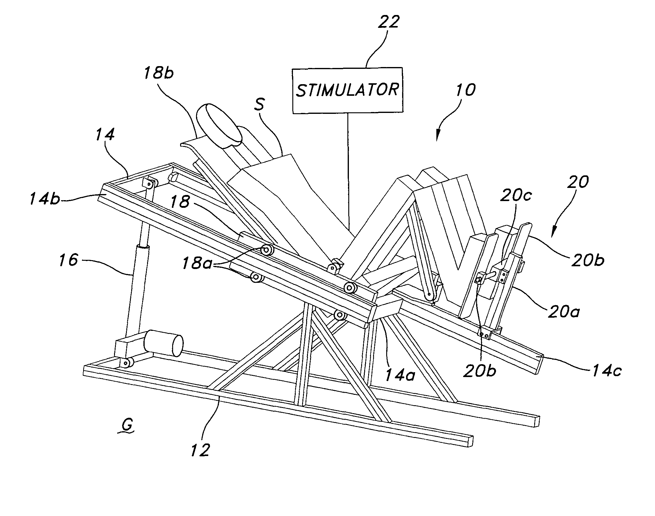
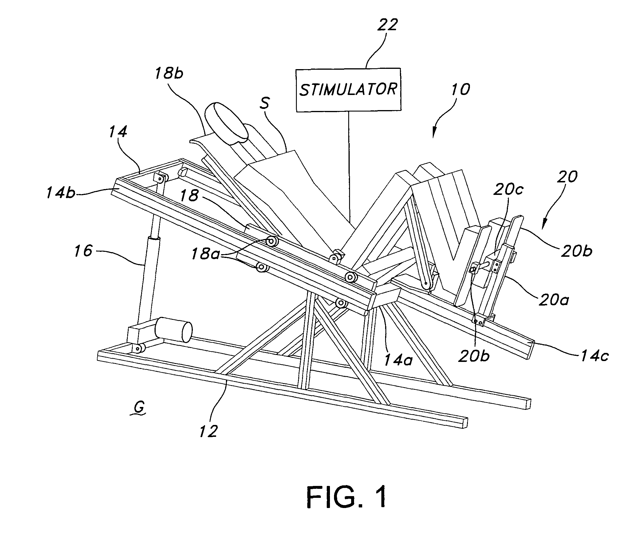
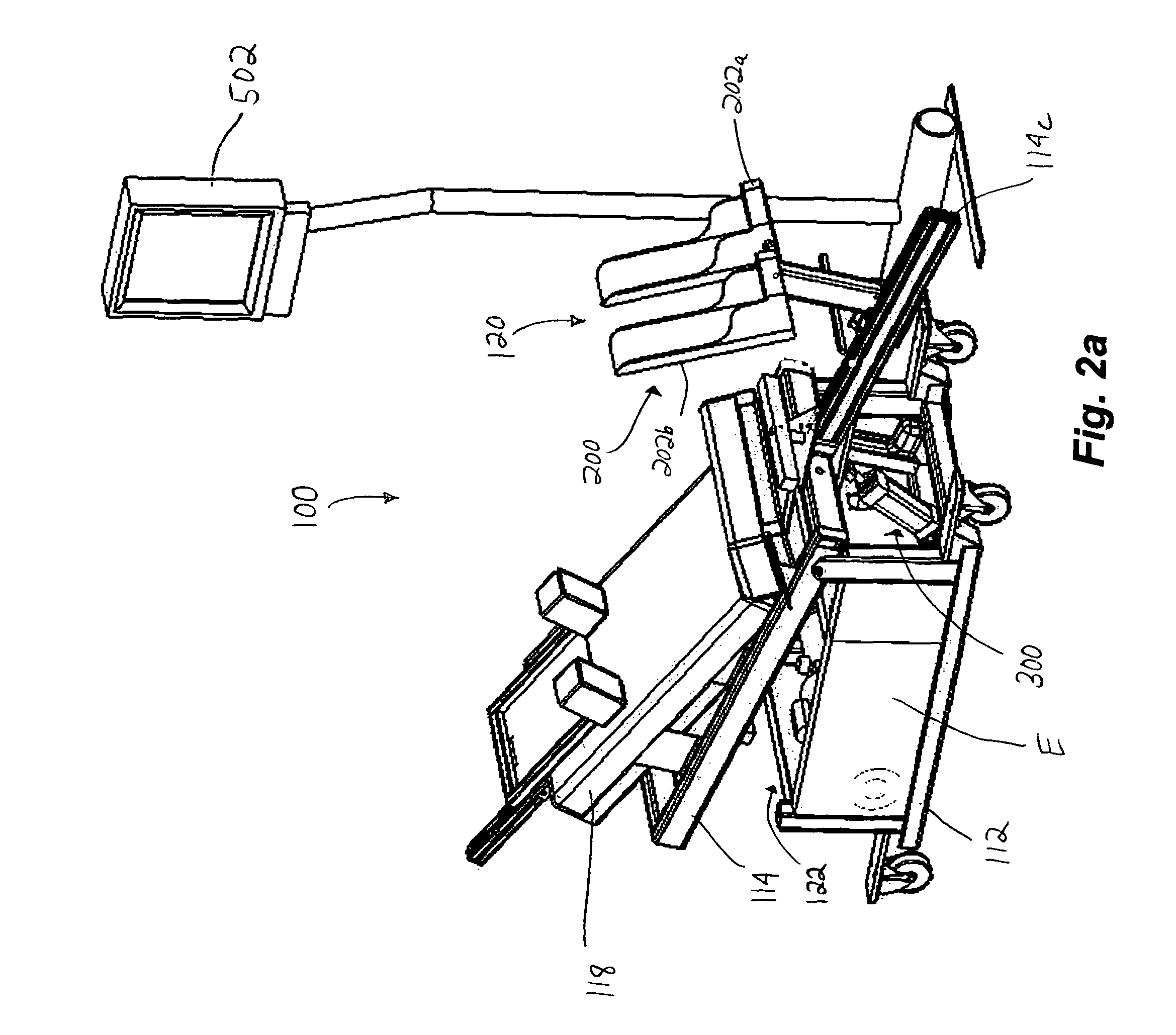
[0048]To facilitate this result, and with reference now to FIGS. 2a and 2b, another embodiment of the exercise device 100 is depicted and described. This device 100 is designed especially to accommodate the application and use of adaptive feedback control, versions of which are generally known in the art. First describing the mechanics, this embodiment of the device 100 includes a base 112, an angularly adjustable frame 114, a sled 118, and an associated stimulator 122, similar to the device 10 outlined in the foregoing description. However, instead of mounting the sled 118 to the frame 114 using rollers, static bearing blocks 118c are shown in FIGS. 3a and 3b as providing the low friction support. These bearing blocks 118c are in turn slidably received in and captured by elongated guide tracks 114d formed in the opposed sides of the frame 114 (FIG. 3b). Consequently, the sled 118 remains fully capable of moving to and fro in a longitudinal direction along the frame 114 between firs...

second embodiment

[0055]With reference back to FIG. 2 and also to FIG. 6, the device 100 of this second embodiment may also include a knee flexion actuator 300, the purpose of which is to serve as a means for unbending the legs from the erect condition, usually once the second position is reached. This flexion actuator 300 in the illustrated embodiment includes a single cross bar 302 adapted for contacting the backs of the subject's knees. This cross bar 302 is in turn connected to an actuator, such as a linear actuator 304, oriented in a generally transverse direction. The linear actuator 304 is in turn mounted to a stable support structure, such as the frame 114 or frame extension 114c.

[0056]In use, the cross bar 302 is normally maintained in a retracted position, such that it lies adjacent to or contacts the backs of the subject's knees only when the legs are fully extended. At that point (which may be detected using the boot angle (or an average thereof), the sled position, the sled height in th...


PUM


Abstract

A device and methods for performing a closed-chain exercise for the lower extremities of a human subject and, in particular, the legs, using stimulation. The device may include a sled for receiving the subject and for translating to and fro between a first, lower position in which the legs are at least partially bent and a second, higher position in which the legs are less bent than in the first position. A stimulator is provided for facilitating the performance of the closed-chain leg exercise by the subject to move the sled between the first and second positions, either by way of electrical signals provided directly to the applicable muscles or by way of sensory (e.g., visual) stimulation, with or without electro-muscular stimulation. In another aspect, adaptive feed-forward control may also be used to enhance the exercise regimen performed using the device.

Description


Claims


Application Information

Patent Timeline
Owner CUSTOMKYNETICS
Learn More