Stackable electrical box

a technology of electrical boxes and boxes, applied in the field of electrical boxes, can solve the problems of difficult storage of electrical boxes in groups, and achieve the effect of reducing the amount of space required

Active Publication Date: 2012-08-28
HUBBELL INC
View PDF18 Cites 8 Cited by
  • Summary
  • Abstract
  • Description
  • Claims
  • Application Information

AI Technical Summary

Benefits of technology

[0013]Particular implementations of a system of electrical boxes may comprise one or more of the following features. In a system of electrical boxes, the first pattern of interfering structures of the first electrical box may comprise at least one rib extending toward the bottom of the first electrical box from adjacent the open top. A system of electrical boxes may further comprise a shoulder formed between the open top and the bottom of the first electrical box such that the bottom of the first electrical box is smaller than the open top of the second electrical box and the shoulder establishes a nesting limit to stop nesting movement of the first electrical box into the second electrical box beyond the shoulder. In a system of electrical boxes, the first pattern of interfering structures of the first electrical box may comprise at least one rib extending toward the bottom of the first electrical box from adjacent the open top. In a system of electrical boxes, the shoulder may be approximately midway between the open top and the bottom of the first electrical box such that nesting of the first electrical box into the second electrical box allows the bottom of the first electrical box to be slid approximately halfway to the bottom of the second electrical box. In a system of electrical boxes, the shoulder may be formed on at least two sides of the first electrical box. In a system of electrical boxes, at least two opposing sides of each of the first electrical box and the second electrical box may be sloped inward along any distance from the open tops of the respective electrical boxes to the bottoms of the respective electrical boxes to accommodate nesting of the first electrical box into the second electrical box and nesting of the second electrical box into the first electrical box.
[0016]Particular implementations of a method of stacking electrical boxes may comprise one or more of the following. A method of stacking electrical boxes may further comprise preventing nesting of first electrical boxes within first electrical boxes by interference between interfering structures of the first pattern on one first electrical box with interfering structures of the first pattern on another first electrical box, and preventing nesting of second electrical boxes within second electrical boxes by interference between interfering structures of the second pattern on one second electrical box with interfering structures of the second pattern on another second electrical box. A method of stacking electrical boxes may further comprise aligning ribs on respective internal surfaces of the first electrical boxes with grooves on external surfaces of the second electrical boxes to permit nesting, and aligning ribs on respective internal surfaces of the second electrical boxes with grooves on external surfaces of the first electrical boxes to permit nesting. A method of stacking electrical boxes may further comprise limiting how far one of the plurality of first electrical boxes nests into one of the plurality of second electrical boxes with a shoulder of the first electrical box contacting the open top of the second electrical box and limiting how far one of the plurality of second electrical boxes nests into one of the plurality of first electrical boxes with a shoulder of the second electrical box contacting the open top of the first electrical box.

Problems solved by technology

Features of electrical boxes typically facilitate installation and improve functionality of the electrical box but these features may also make compact storage of groups of electrical boxes difficult.

Method used


Image

  • Stackable electrical box
  • Stackable electrical box
  • Stackable electrical box

Examples


Embodiment Construction

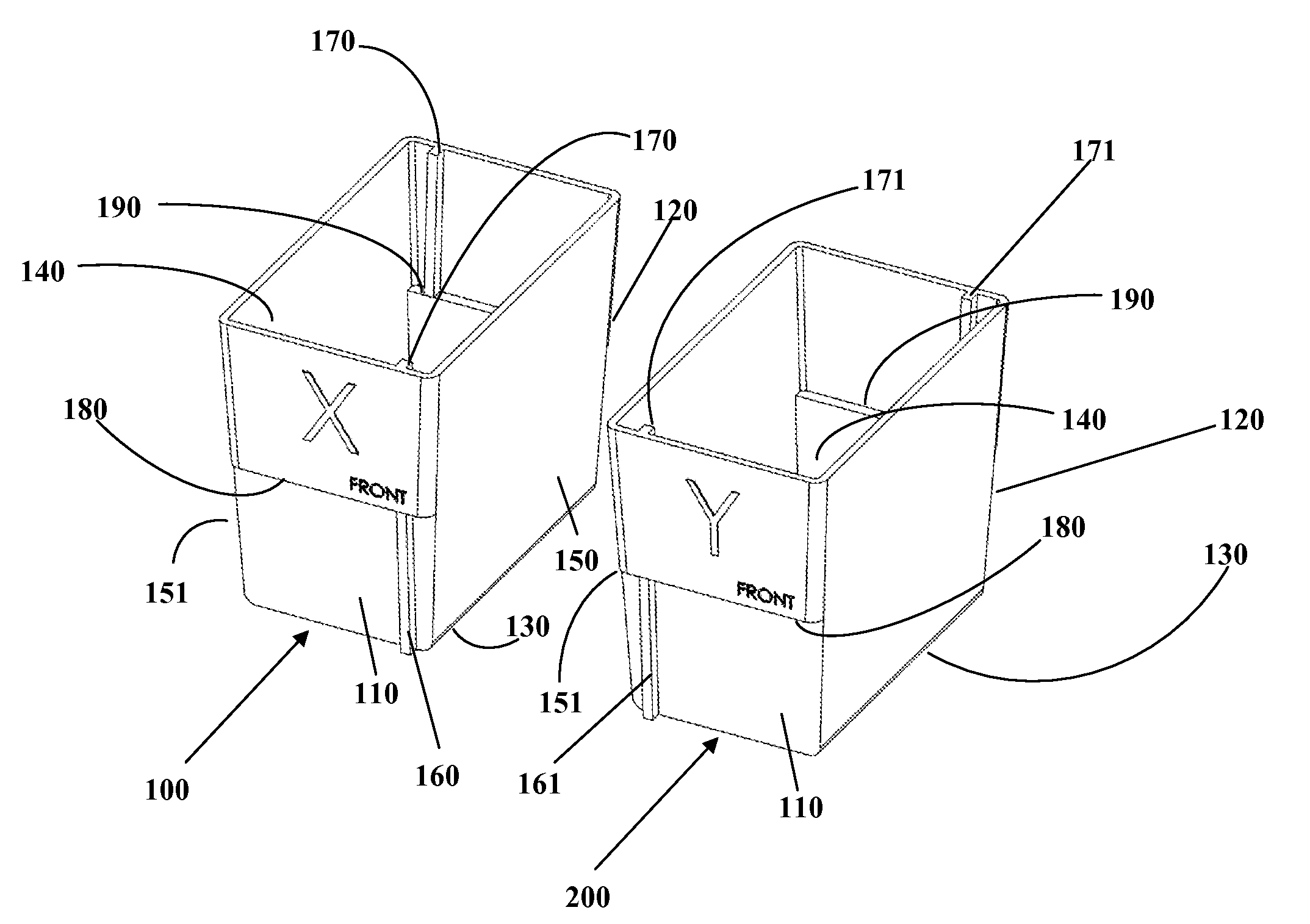
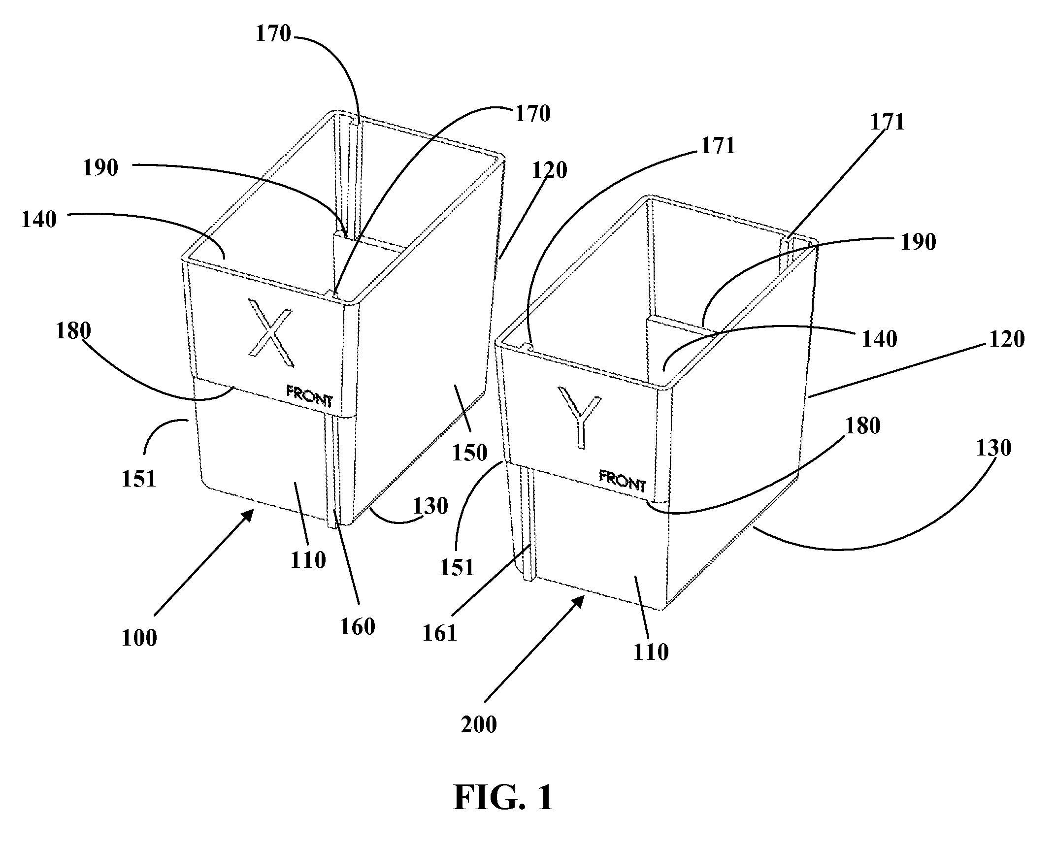
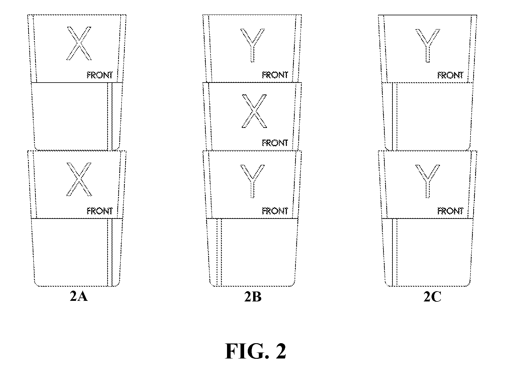
[0024]This disclosure, its aspects and implementations, are not limited to the specific components or assembly procedures disclosed herein. Many additional components and assembly procedures known in the art consistent with the intended electrical boxes and / or assembly procedures for electrical boxes may be used and will become apparent for use with particular implementations from this disclosure. Accordingly, for example, although particular implementations are disclosed, such implementations and implementing components may comprise any shape, size, style, type, model, version, measurement, concentration, material, quantity, and / or the like as is known in the art for such electrical boxes and implementing components, consistent with the intended operation and purpose of electrical boxes. As used herein, “electrical boxes” is intended to specifically refer to the types of electrical boxes that are mounted within a wall structure and to which small electrical devices such as electric...


PUM


Abstract

A method and structure of a system of electrical boxes including differing patterns of interference structures, such as ribs and / or grooves, to prevent identical boxes from being nested but permit non-identical boxes from being nested for more space-efficient storage of electrical boxes.

Description

CROSS REFERENCE TO RELATED APPLICATIONS[0001]This Application claims the benefit of the filing date of U.S. Provisional Patent Application 61 / 181,909 to Cleghorn entitled “Electrical Box,” which was filed on May 28, 2009, the disclosure of which is hereby incorporated herein by reference.BACKGROUND OF THE INVENTION[0002]1. Technical Field[0003]Aspects and implementations of this document relate generally to electrical boxes. Particular implementations include electrical boxes designed to be nested with each other in a variety of ways (e.g., vertically stacked in a nested configuration) for storage, shipment, and the like.[0004]2. Background Art[0005]Electrical boxes are well known in the art of the electrical installation aspects of construction to house electrical components of such things as switches and receptacles. Conventional electrical boxes are typically one-piece structures with external features that make them somewhat voluminous. Therefore, it is desirable to improve the ...

Claims


Application Information

Patent Timeline
Patent Type & Authority Patents(United States)
IPC IPC(8): H02G3/08
CPCH02G3/081
Inventor BALDWIN, JEFFREY P.CLEGHORN, RICHARD L.
Owner HUBBELL INC
Why Eureka
Try Eureka