

System and method for mounting of audio-visual components
a technology for audio-visual components and mounting systems, which is applied in the direction of transducer diaphragms, electrical apparatus casings/cabinets/drawers, instruments, etc., can solve the problems of insufficient sound reproduction accuracy of the typical provided sound, small size, and inability to meet the needs of the display,
- Summary
- Abstract
- Description
- Claims
- Application Information
AI Technical Summary
Benefits of technology
Problems solved by technology
Method used
Image

Examples
Embodiment Construction
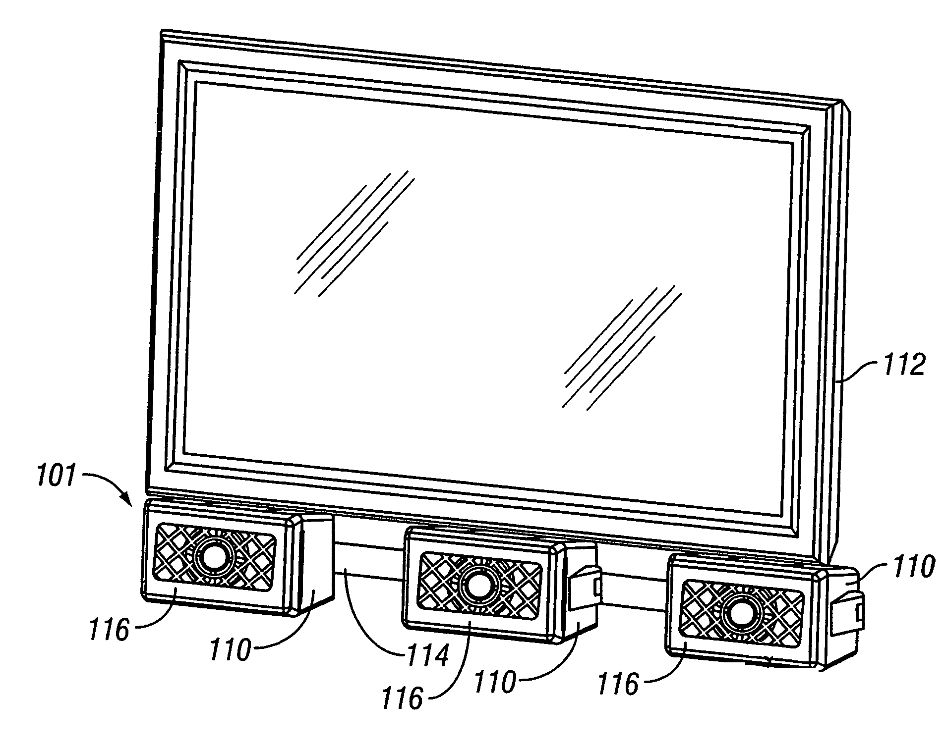
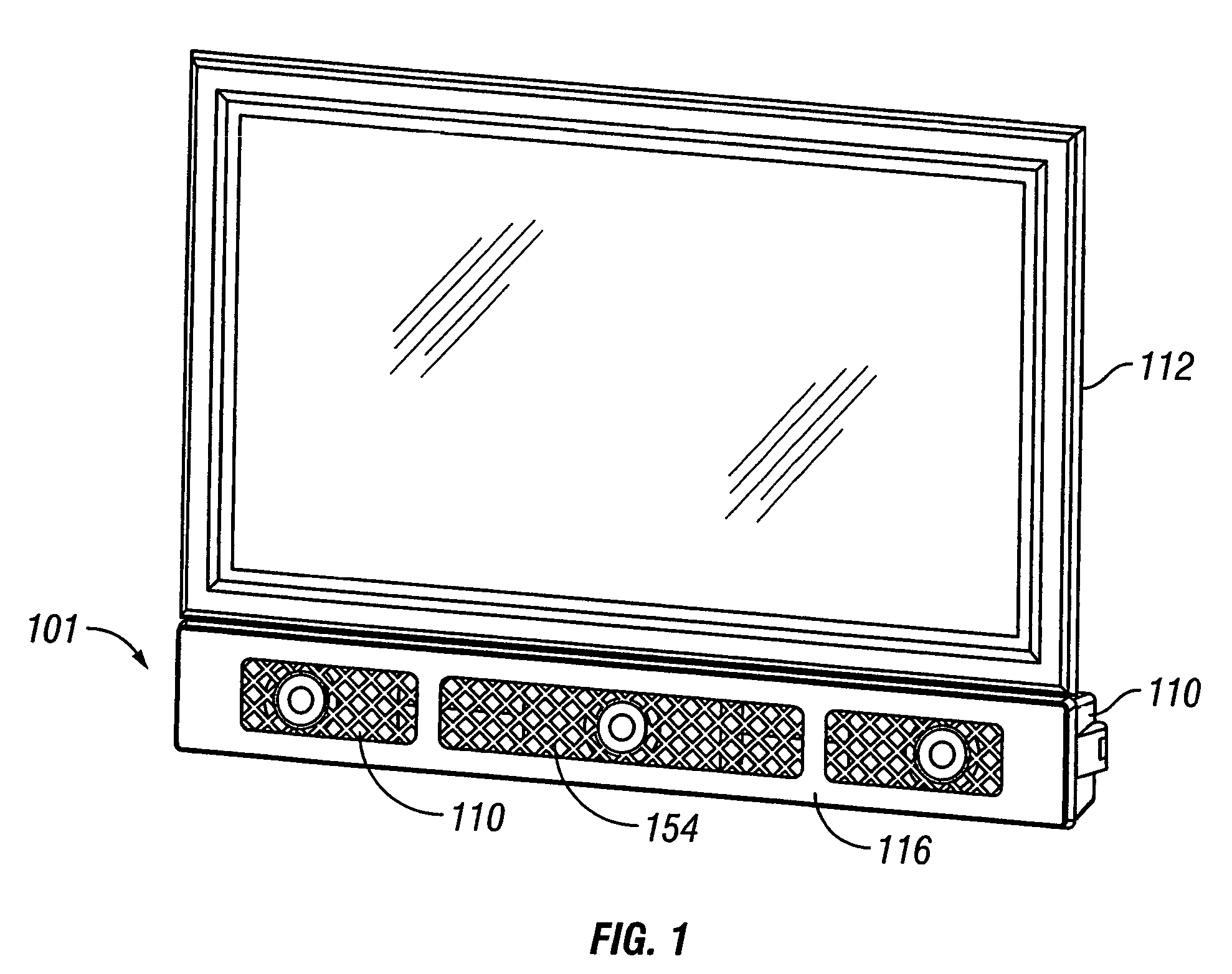
” one will understand how the features of this invention provide advantages that include increased ease of wall mounting the components of an audio-visual system.
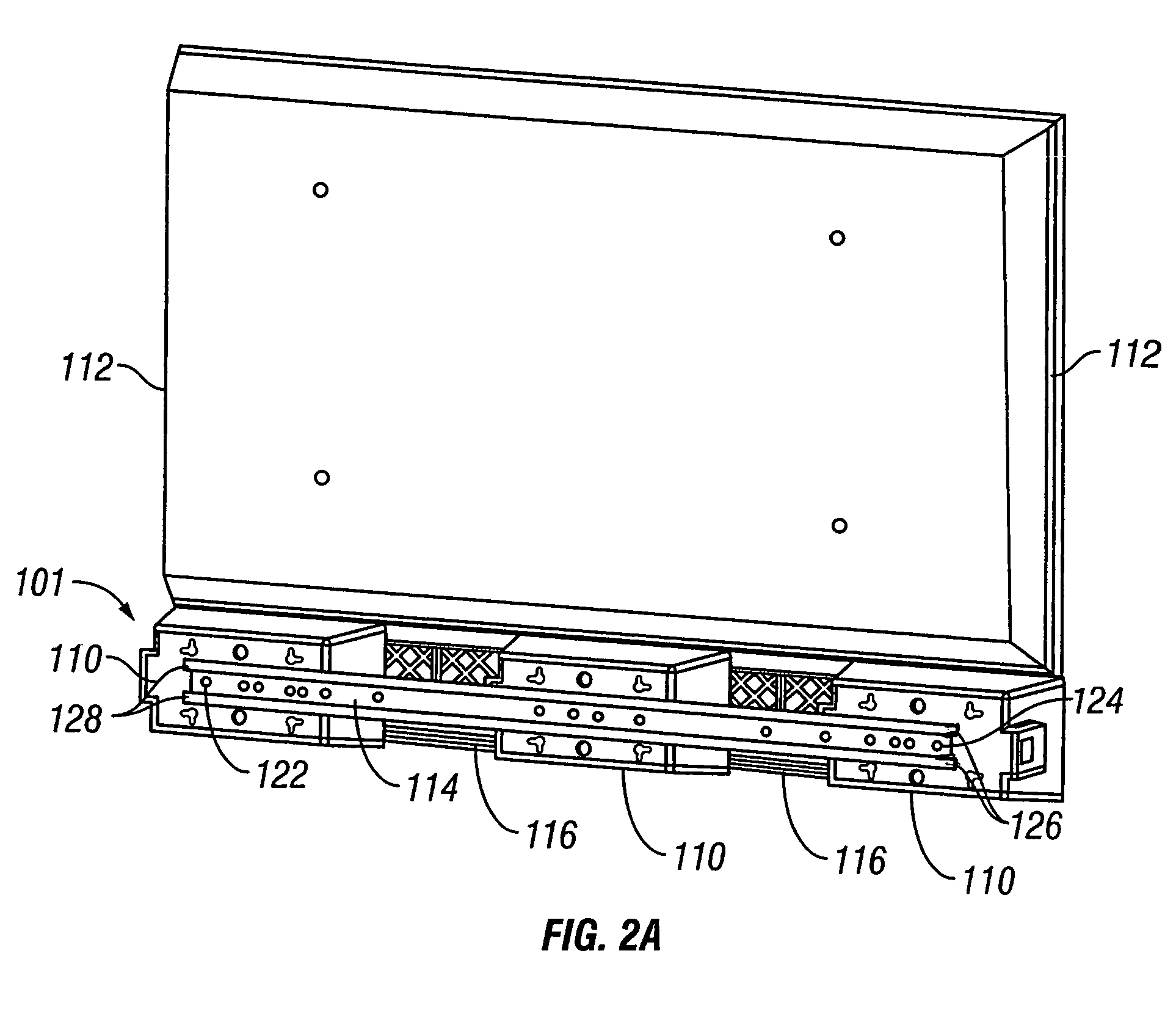
[0013]One embodiment is a modular mounting bar for securing components to a surface. The system comprises a plurality of audio-visual modules. A rail is configured to be attached to the surface at one of a plurality of locations along the rail. The rail is also configured to receive a module at one of a plurality of locations along the rail. A cover may be configured to be secured in front of at least a portion of one of the modules.
[0014]Another embodiment is a modular mounting system for audio-visual components. The system comprises at least one audio-visual module. A rail may be configured to be attached to a surface, and may be configured to receive the module.
[0015]Another embodiment is a method of mounting audio-visual components to a surface. A rail is provided which has portions thereof that define a channel. The ra...
PUM
 Abstract
Description
Claims
Application Information