Closure system for braces, protective wear and similar articles
What is AI technical title?
AI technical title is built by Patsnap AI team. It summarizes the technical point description of the patent document.
a technology of braces and closures, applied in the direction of shoe lace fastenings, nuclear engineering, nuclear elements, etc., can solve the problems of bulky fittings used to couple straps, discomfort and restriction of circulation, shift of orthopedic braces, etc., and achieve the effect of facilitating opening and closing and low friction interfa
Active Publication Date: 2012-10-02
BOA TECHNOLOGY
View PDF372 Cites 135 Cited by
Summary
Abstract
Description
Claims
Application Information
AI Technical Summary
This helps you quickly interpret patents by identifying the three key elements:
Problems solved by technology
Method used
Benefits of technology
Benefits of technology
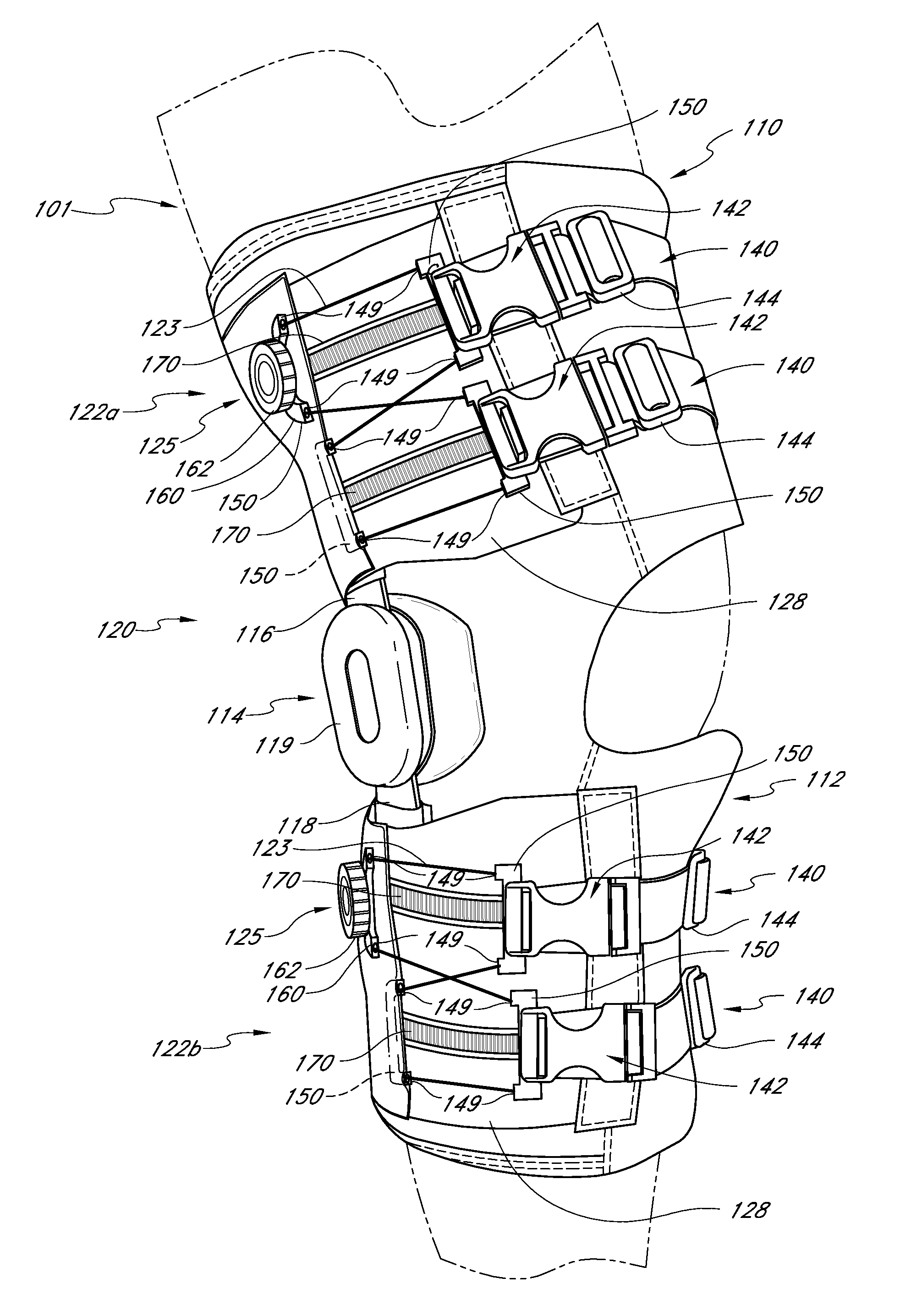
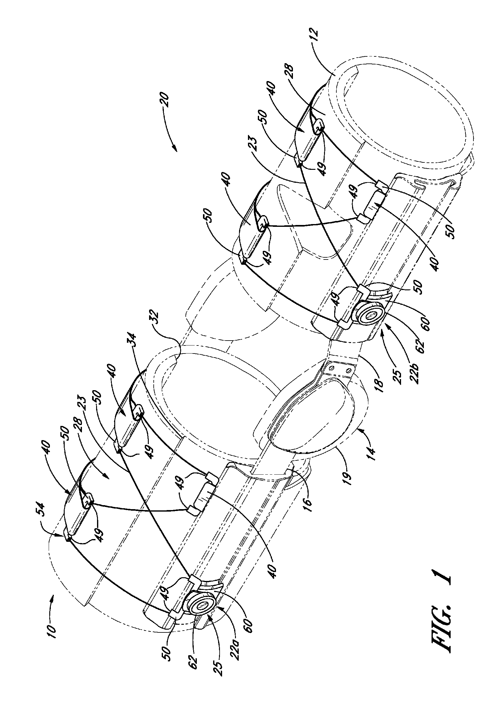
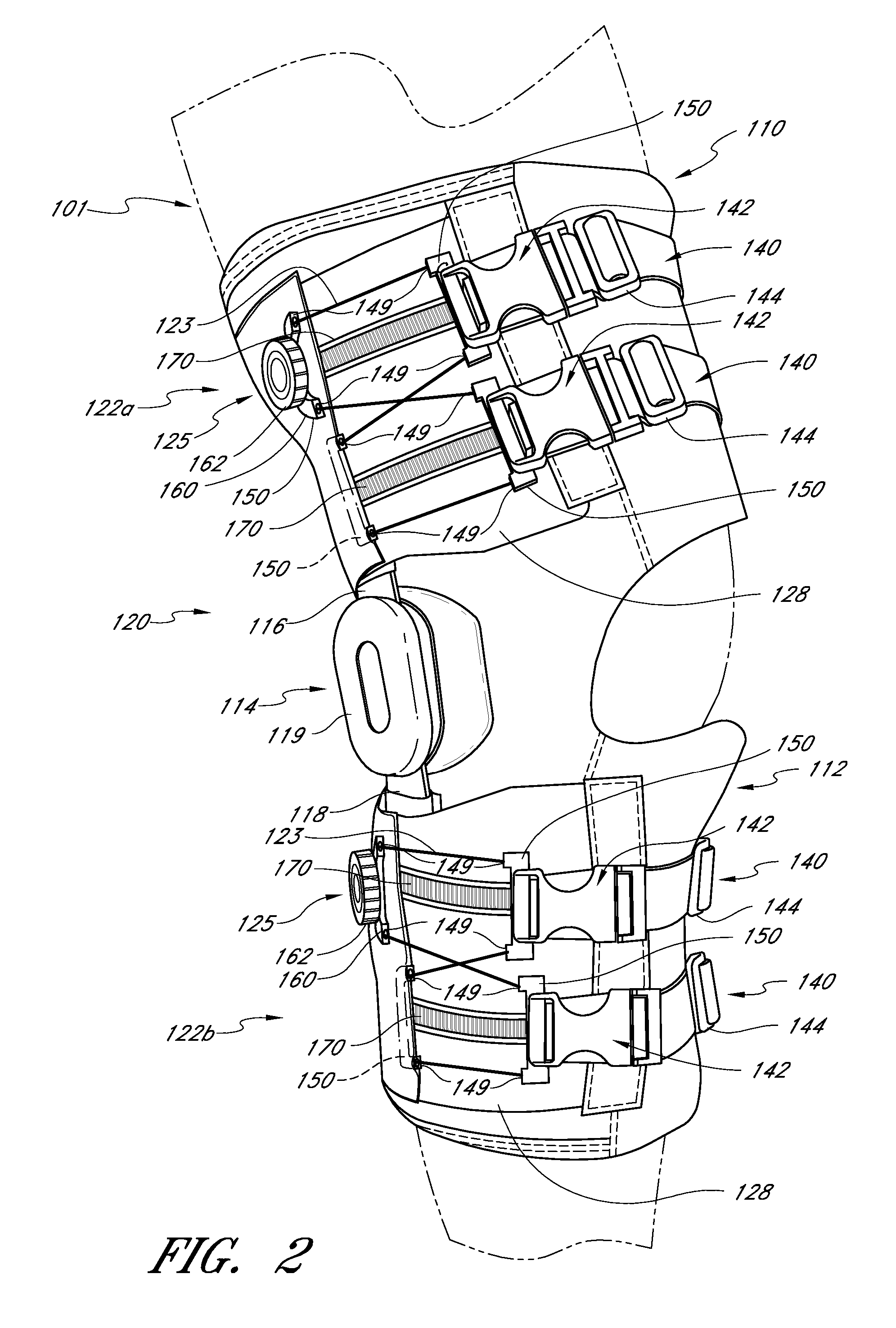
[0014]In some embodiments, a closure system for an article of protective wear is provided including at least one set of opposed guide members and a lace extending back and forth between the opposed guide members, the guide members and lace having a relatively low friction interface therebetween. A rotatable tightening mechanism is also provided and configured to apply tension on the lace, thereby advancing the opposed guide members towards each other. The system also includes a retaining member coupled by a quick release member to one of the opposed guide members, the retaining member configured to extend across an opening in the protective wear and the release member configured to facilitate opening and closing of the system, wherein the tightening mechanism permits final adjustment of the tension in the system.
[0015]In some embodiments, a brace closure system includes a brace with a plurality of opposing lace guide members attached thereto. A lace extends through the guide members and a rotatable tightening mechanism is attached to the brace and coupled to the lace, the tightening mechanism including a housing and a control for retracting the lace into the housing to place tension on the lace thereby tightening the brace.
[0016]In some embodiments, a method of closing an article comprising a closure system comprising a pair of opposing lace guides, a rotatable tightening mechanism comprising a housing and a control, a lace coupling the pair of lace guides and the tightening mechanism, a retaining member, and a release mechanism having a first component selectively couplable to a second component, wherein the first component is coupled to a lace guide and the second component is coupled to a retaining member includes the steps of coupling the first and second components of the release mechanism to couple the retaining member to the guide and rotating the control to draw the lace into the housing, thereby increasing the tension on the lace and drawing the opposing lace guides toward each other, wherein the guide members and the lace have a relatively low friction interface therebetween and the lace is permitted to slide through the guide members to equilibrate the tension in the system.
Problems solved by technology
One significant problem with orthopedic braces used during athletic activities is the tendency of the orthopedic braces to shift as adjacent muscles tense and relax.
When this problem is approached by tightening a conventional strapping mechanism, discomfort and restriction of circulation occurs.
Even partial shifting of a typical orthopedic brace interferes with its proper operation, and so an athlete must choose between a properly oriented brace and a comfortable one.
Another problem with conventional braces is the bulky fittings used to couple straps.
Whenever the cuff structures have such extraneous additional structure for fitting the straps, user discomfort is increased from the added bulk and complexity, and a low profile is difficult to achieve.
Yet another problem with conventional braces is the lack of even compression of the soft tissues of the leg against the internal structure of the bones whose position and movement are to be controlled.
The typical strapping mechanism often does not adequately distribute the tightening force along the length of a tightening zone.
Another drawback associated with conventional strapping mechanisms is that it is often difficult to untighten or redistribute tension, as the wearer must loosen and readjust the straps and brace positioning.
Similar problems are present when protective wear or other articles or equipment are strapped to various parts of the body of a human or other animal.
Method used
Image
Click on the blue label to locate the original text in one second.
Reading with bidirectional positioning of images and text.
Examples
Embodiment Construction
[0035]Referring to FIG. 1, one embodiment of an orthopedic brace 20 prepared in accordance with the present inventions is disclosed. The orthopedic brace 20 generally comprises a knee brace that is tightened around a wearer's leg using a lacing configuration comprising two lacing systems 22a, 22b, such that the knee brace substantially surrounds and protects the wearer's knee. The orthopedic brace of the illustrated embodiment is particularly concerned with relieving and / or supporting the knee joint.
[0036]Generally speaking, some knee braces function to counteract anterior shifting of the tibia when the anterior cruciate ligament is missing or damaged. Such anterior shifting of the tibia may occur for a variety of reasons and often happens when a person engages in physical activities that involve sudden turning to the right or to the left, sudden stopping, sudden jumping, running backwards or other types of movements. Where the anterior cruciate ligament is missing or damaged, such ...
PUM
Abstract
A closure system for braces, protective wear and similar articles is disclosed. The closure system includes a plurality of opposing lace guide members and a tightening mechanism. The closure system further includes a lace extending through the guide members and coupled to the tightening mechanism. In some embodiments, a quick release apparatus is included to facilitate opening of the closure system. The tightening mechanism in some embodiments includes a control for winding the lace into a housing to place tension on the lace thereby tightening the closure system.
Description
[0001]This application claims the benefit of U.S. Provisional Patent Application No. 60 / 843,830, filed Sep. 12, 2006.[0002]This application hereby incorporates by reference in their entireties U.S. patent application Ser. No. 11 / 263,253, filed Oct. 31, 2005, published Jul. 20, 2006 under publication number 2006-0156517 A1, pending, U.S. patent application Ser. No. 11 / 650,665, filed Jan. 8, 2007, published Jul. 25, 2007 under publication number 2007-0169378 A1, pending, and U.S. Provisional Patent Application No. 60 / 843,830, filed Aug. 12, 2006.[0003]These inventions relate to braces, protective wear and similar articles worn on the body or appendages of humans and animals. More particularly, these inventions relate generally to low-friction closure systems that provide equilibrated tightening pressure for a brace, protective wear or other similar article.BACKGROUND OF THE INVENTION[0004]Orthopedic supports are typically used to stabilize and protect various limbs of the human anatom...
Claims
Application Information
Patent Timeline
Application Date:The date an application was filed.
Publication Date:The date a patent or application was officially published.
First Publication Date:The earliest publication date of a patent with the same application number.
Issue Date:Publication date of the patent grant document.
PCT Entry Date:The Entry date of PCT National Phase.
Estimated Expiry Date:The statutory expiry date of a patent right according to the Patent Law, and it is the longest term of protection that the patent right can achieve without the termination of the patent right due to other reasons(Term extension factor has been taken into account ).
Invalid Date:Actual expiry date is based on effective date or publication date of legal transaction data of invalid patent.

