
Fast acting switching valve train system for valve deactivation

a switching valve train and valve deactivation technology, applied in the direction of engines, mechanical equipment, machines/engines, etc., can solve the problems of high operating range of allowable deactivation mode, large size and mass of switching valve train components, and often limited oil temperature operating range, so as to improve system stiffness and actuation time, and reduce friction interface

Active Publication Date: 2017-07-13
SCHAEFFLER TECH AG & CO KG
View PDF3 Cites 11 Cited by
  • Summary
  • Abstract
  • Description
  • Claims
  • Application Information

AI Technical Summary

Benefits of technology

The patent provides a fast-acting switchable rocker arm system for valve deactivation that enables a full valve lift event. The system includes a switchable rocker arm and an actuator assembly that work independently of each other. The switchable rocker arm rotates about the rocker shaft and includes a valve arm assembly and a cam arm assembly. When in the locked mode, the valve side arm assembly is coupled to the cam side arm assembly and allows for a full valve lift event. To achieve an unlocked mode, the actuator assembly vertically extends an actuator pin that forces the shuttle pin to move against the locking pin and the bias spring force, disengaging the valve arm assembly. The unlocked mode allows for control and position of the cam side arm assembly during operation without any valve lift. A lost motion spring can be used to maintain control and position of the cam side arm assembly during the unlocked condition. The cam side arm assembly can also include a cam roller follower to provide a low friction interface with the camshaft. The actuator pin and the shuttle pin can have different embodiments, and the system can even include a hydraulic lash adjuster for maintenance-free valve lash control. Improved stiffness and actuation time can be achieved by supporting the actuator pin and the shuttle pin with a housing or other alternative structure within the engine.

Problems solved by technology

With simultaneous multiple cylinder control, the timing of the valve deactivation event with respect to the combustion cycle is not controlled to the extent of the selective cylinder control resulting in intermittent exhaust charge trapping.
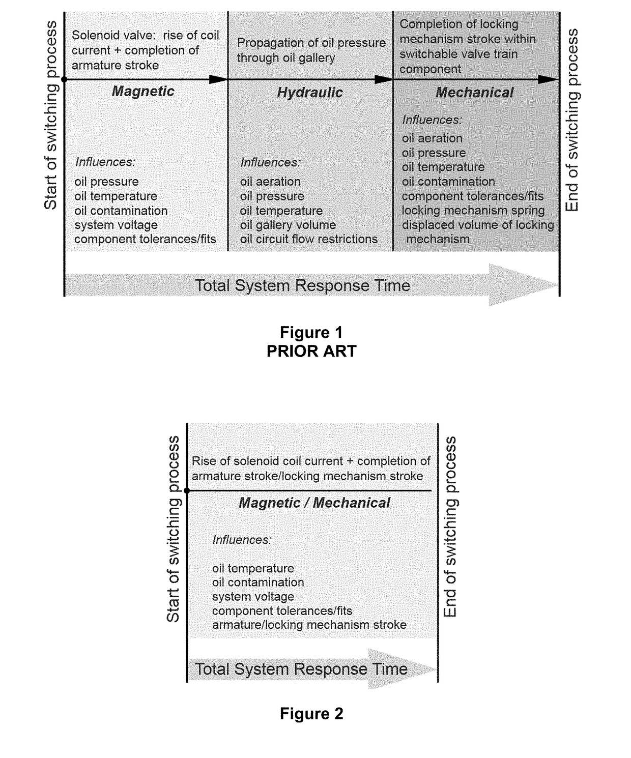
For this reason, the allowable deactivated mode operating range is often limited by oil temperature due to increased system response times with reduced oil temperatures.
Switching valve train components are often larger in size and mass when compared to non-switching or standard valve train components and remains a constant challenge.
Such a force increase often equates to increased stresses, wear, and friction between rubbing interfaces of the valve train system.

Method used


Image

  • Fast acting switching valve train system for valve deactivation
  • Fast acting switching valve train system for valve deactivation
  • Fast acting switching valve train system for valve deactivation

Examples


Embodiment Construction

[0028]Identically labeled elements appearing in different figures refer to the same elements but may not be referenced in the description for all figures. The exemplification set out herein illustrates embodiments which should not be construed as limiting the scope of the claims in any manner.

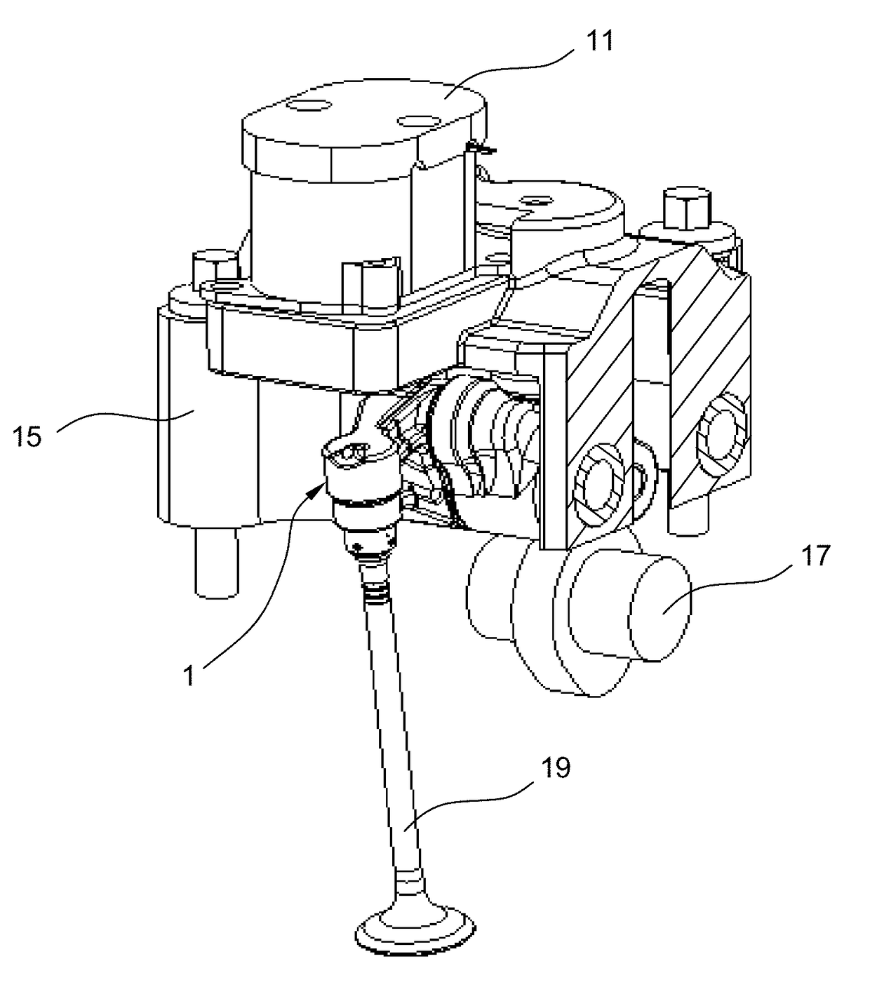
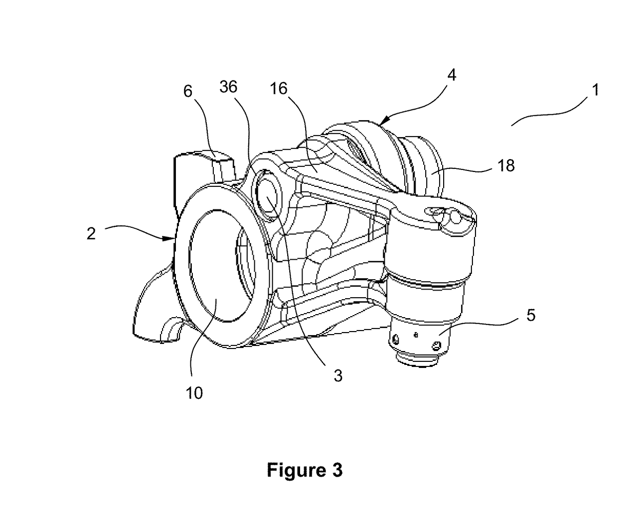
[0029]Referring to FIG. 3, a fast-acting switchable rocker arm 1 for valve deactivation is shown that can achieve fast actuation and reactivation times to meet the demands of new cylinder deactivation systems. Referring now to FIG. 4, a fast-acting switchable rocker arm system 30 is shown that includes the switchable rocker arm 1 of FIG. 3 together with an actuator 11 that controls an actuator pin 13. FIG. 5 shows the fast-acting switchable rocker arm system 30 of FIG. 4 within a switchable valve train system 40. FIG. 6 shows the switchable valve train system 40 within a sectioned cylinder head 15 of an IC engine. FIG. 7A shows the switchable rocker arm 1 in a locked condition while FIG. 8A sho...


PUM


Abstract

A fast acting valve train system for valve deactivation is provided that includes an actuator together with a switchable rocker arm. The actuator, controlled by the engine control unit and mounted to a structural housing, contains an actuator pin that retracts or extends facilitating either a deactivation or reactivation valve event. The switchable rocker arm is a two arm design that includes cam side and valve side arms that are coupled together with a locking mechanism assembly that interfaces with the actuator pin. The system is capable of fast switching times to meet the increased demands of cylinder deactivation systems.

Description

TECHNICAL FIELD[0001]Example aspects described herein relate to valve train systems that are used in internal combustion engines to actuate one or more intake and / or exhaust valves, and, more particularly, valve train systems that are used for selectively switching between full lift and no lift modes for one or more intake and / or exhaust valves.BACKGROUND[0002]More stringent fuel economy regulations have prompted the need for improved efficiency of the internal combustion (IC) engine. Lightweighting, friction reduction, thermal management, variable valve timing and a diverse array of variable valve lift technologies are all part of the technology toolbox for IC engine designers.[0003]Variable valve lift (VVL) systems typically employ a technology in a valve train of an IC engine that allows different engine valve lifts to occur. The valve train consists of the components that are required to actuate an engine valve, including a camshaft, the valve and all components that lie in betw...

Claims


Application Information

Patent Timeline
Patent Type & Authority Applications(United States)
IPC IPC(8): F01L1/20F01L1/18F16H53/06
CPCF01L1/205F01L1/181F16H53/06F01L1/053F01L1/2416F01L13/0005F01L2001/186F01L2013/001F01L2013/101F01L2305/00
Inventor HAEFNER, DONALD
Owner SCHAEFFLER TECH AG & CO KG
Learn More