Brake system stabilizer assembly

a technology of brake system and stabilizer, which is applied in the direction of brake system, brake arrangement with braking member, transportation and packaging, etc., can solve the problems of severe vibration, wear and distorted members, and the inability to properly align the brake shoes with the wheels

Inactive Publication Date: 2011-02-22
MALACHOWSKI JEROME A
View PDF9 Cites 0 Cited by
  • Summary
  • Abstract
  • Description
  • Claims
  • Application Information

AI Technical Summary

Benefits of technology

[0004]The present invention appends a stabilizing member in an area of the brake system used to transmit applied brake forces from an actuating cylinder to the brake beam. This member greatly improves the control of the spatial orientation of a modified brake beam within a railway vehicle truck and provides lateral support to a truck lever connector and levers, which in turn, properly locate actuating bars of the brake system.
[0005]The main object of the present invention is to provide a stabilizer that can be appended to the applied brake force path in_brake rigging assemblies of various railway vehicles to counteract the adverse torque imposed on a brake beam during brake applications. The use of the present invention causes an improved operating alignment between installed brake shoes and the railway vehicle wheels.
[0006]A second object of the present invention is to provide a stabilizer that can be appended to the applied brake force path in_brake rigging assemblies of various railway vehicles to provide desired alignment and a resulting low friction interface between end guides of the brake beam and unit guide wear liners installed in the side frames.
[0007]A third object of the present invention is to provide a stabilizer that can be appended to the applied brake force path in brake rigging assemblies of various railway vehicles to increase the useful life of railway cars and their wheels by reducing vibration from damaged wheels, as frequently occur when using a prior art support means for the braking system.
[0010]It is a further object of the present invention to provide controlled angular alignment of a connector that is pinned to levers supported in brake beams.
[0011]It is yet a further object of the present invention to provide a stabilizer that causes a brake lever to have guided lateral support, which in turn controls the location of a top actuating bar in the applied brake force path.

Problems solved by technology

In the prior art, the generated braking torque eventually coerces_the brake shoes away from the desired alignment with the wheel tread surfaces.
The brake friction forces often cause severe vibration in the previously mentioned supporting members.
These members become worn and distorted.
At some point in time, they are no longer able to properly align the brake shoes with the wheels.
This uneven brake shoe wear requires premature replacement, wherein a considerable amount of brake friction material is resultingly discarded as unusable.
Brake shoe maintenance costs are higher than necessary.
Other progressive damage also occurs to brake beams, levers and actuating bars of the brake system.
The progressive damage causes misalignments, reduces the available braking force and renders the involved train less safe.

Method used


Image

  • Brake system stabilizer assembly
  • Brake system stabilizer assembly
  • Brake system stabilizer assembly

Examples


Embodiment Construction

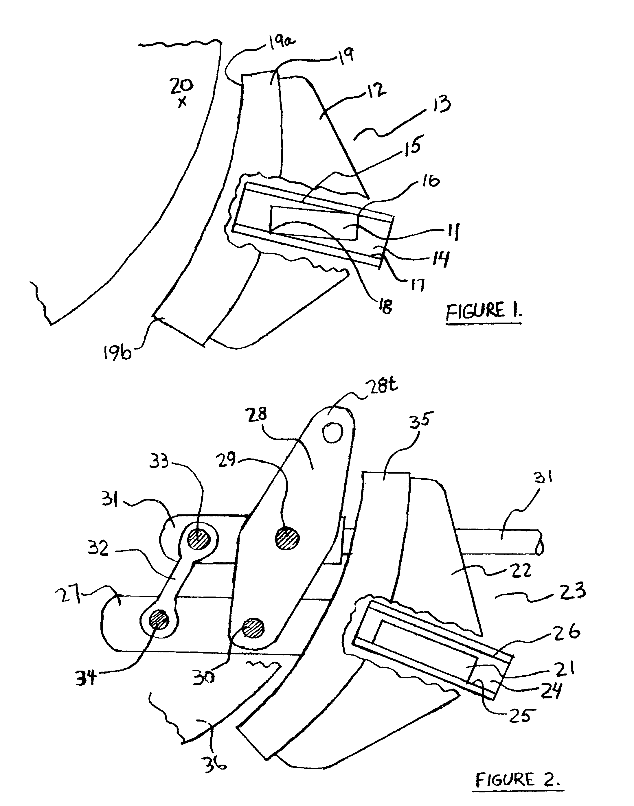
[0018]In FIG. 1, end guide 11 and brake head 12 are parts of brake beam assembly 13 in the prior art. Brake shoe 19 is installed and fastened in brake head 12. End guide 11 is positioned within upper surface 15 and lower surface 17 of wear liner 14 (visible in the cut-out areas of brake head 12 and brake shoe 19). End guide 11 may make contact with inside surfaces 15 and 17 at corners 16 and 18 when the brakes are applied.

[0019]Repeated brake applications may cause end guides 11 and wear liner 14 to wear away at areas 16 and 18. These worn areas allow end guide 11, brake head 12, brake beam assembly 13 and brake shoe 19 to rotate in a counter-clockwise direction as depicted in this figure. In this orientation, wear of brake shoe 19 will be greater in the top area 19a compared to bottom area 19b. At some point in time, top area 19a will wear to the minimum thickness allowed while a large fraction of the brake friction material originally available at bottom area 19b still remains. At...


PUM


Abstract

The present invention adds a stabilizing force member to prior art Railway brake systems and greatly improves the control of the spatial orientation of a modified brake beam within a Railway vehicle and provides lateral support to a truck lever connection and levers, which in turn, properly locate actuating bars of the brake system. As a result, service life of brake beam support components and brake shoes are extended, brake lever friction is reduced and brake system efficiency is increased.

Description

BACKGROUND OF THE INVENTION[0001]Brake Systems-on Railway vehicles employ force transmitting members, including brake beams to provide train braking forces. A primary suspension_means for the brake beams can take the form of end guides located at each end of the brake beam. These are positioned and supported within unit guide wear liners which are, in turn, installed in the railway truck frames. This suspension also acts to react the torque generated by braking, and initially positions and aligns the frictional brake shoes with the wheel tread surfaces in an acceptable manner.[0002]In the prior art, the generated braking torque eventually coerces_the brake shoes away from the desired alignment with the wheel tread surfaces. The brake friction forces often cause severe vibration in the previously mentioned supporting members. These members become worn and distorted. At some point in time, they are no longer able to properly align the brake shoes with the wheels.[0003]Consequently, th...

Claims


Application Information

Patent Timeline
Patent Type & Authority Patents(United States)
IPC IPC(8): F16D65/14
CPCB61H1/00B61H13/36
Inventor MALACHOWSKI, JEROME A.
Owner MALACHOWSKI JEROME A
Why Eureka
Try Eureka