Hot-wire cutter

a cutter and wire cutter technology, applied in the field of hot wire cutters, can solve the problems of inability to retain the center of processing, large labor and time required to have the job done, and errors in the cutting angle of the final product of the work piece, so as to facilitate the processing of sections

Inactive Publication Date: 2012-10-02
EXCETEK TECH INC
View PDF4 Cites 0 Cited by
  • Summary
  • Abstract
  • Description
  • Claims
  • Application Information

AI Technical Summary

Benefits of technology

[0008]To achieve the foregoing objective, the hot-wire cutter includes a frame, a tank supported on the frame, a first working head located on a floor of the tank, a second working head movably supported on the frame, a supporting unit supported on the frame and used to support the annular work piece, a restraining unit supported on the frame and used to clamp the annular work piece, and a rotating unit supported on the frame and used to rotate the annular work piece. Thus, a line between the first and second working heads is directed through the centers of initial apertures in the annular work piece, one after another, to facilitate precise processing of sections of the annular work piece corresponding to the initial apertures.

Problems solved by technology

However, if the work piece is an annular element, and apertures are to be made in the work piece in radial directions, much labor and time are required to have the job done.
Moreover, the center of processing cannot be retained, and initial apertures must be located in a line.
Hence, there will be errors in the angles of the cutting in the final product of the work piece if the conventional hot-wire cutter moves the work piece in an XY plane to find the centers of the initial apertures of the annular work piece.

Method used


Image

  • Hot-wire cutter
  • Hot-wire cutter
  • Hot-wire cutter

Examples


Embodiment Construction

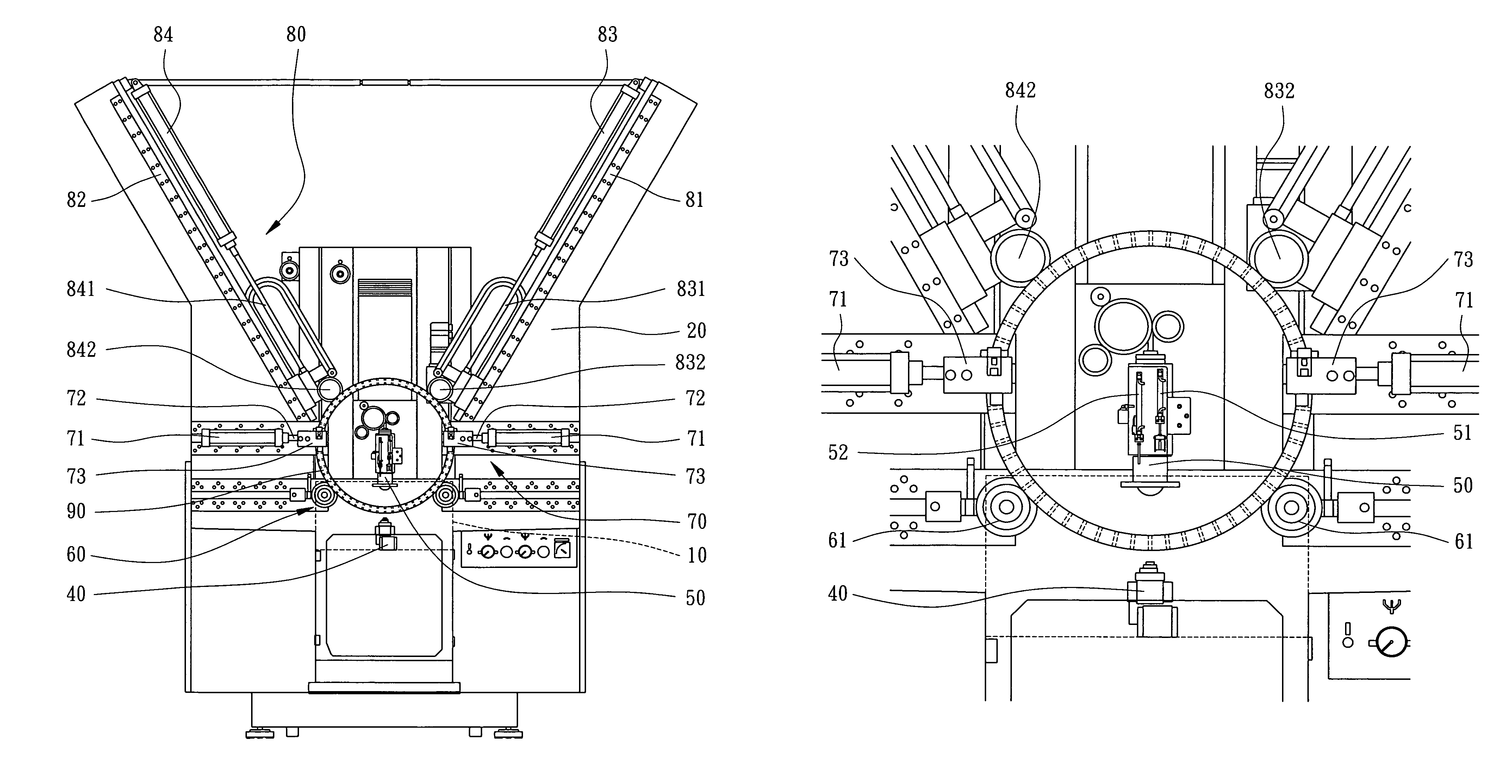
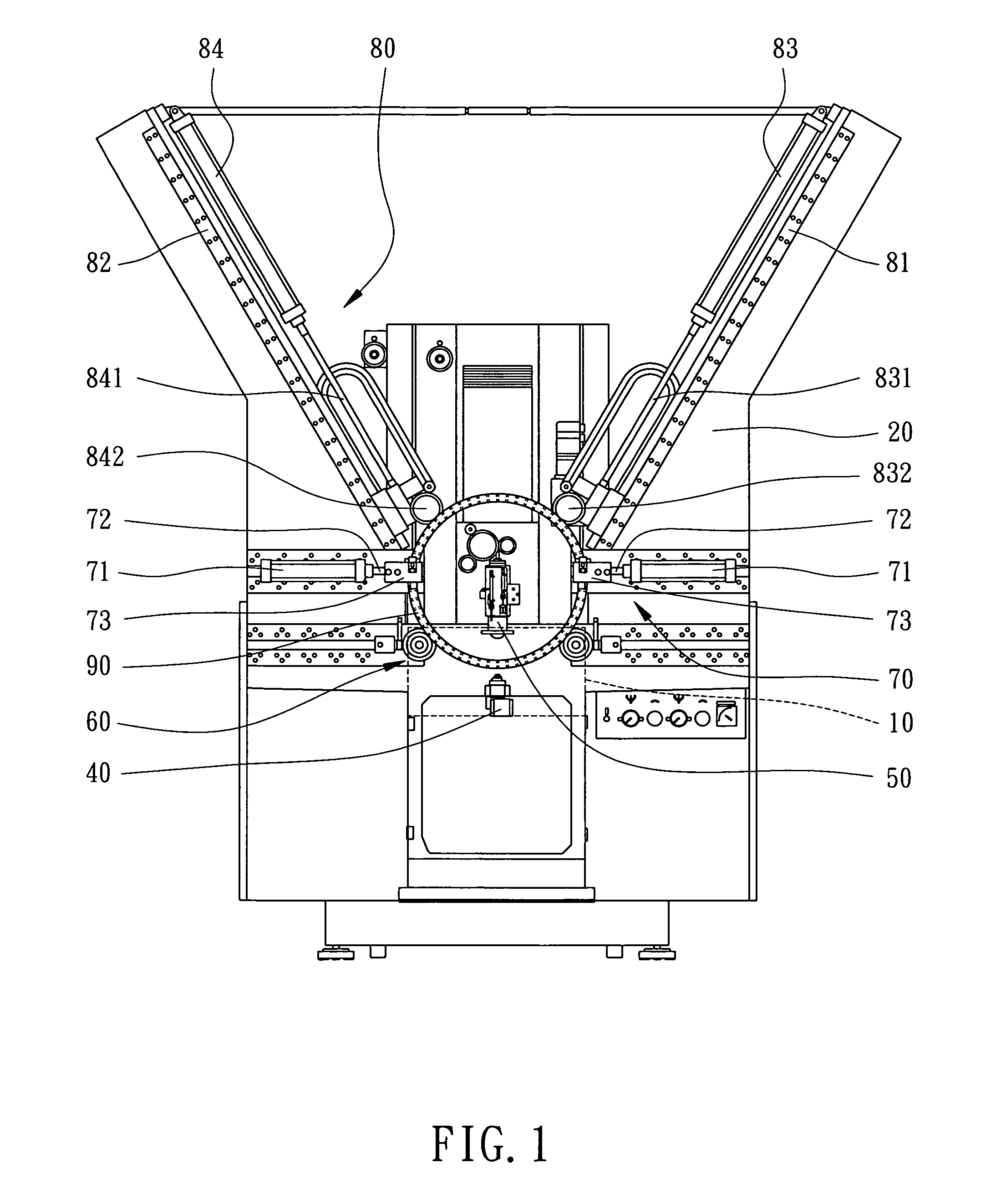
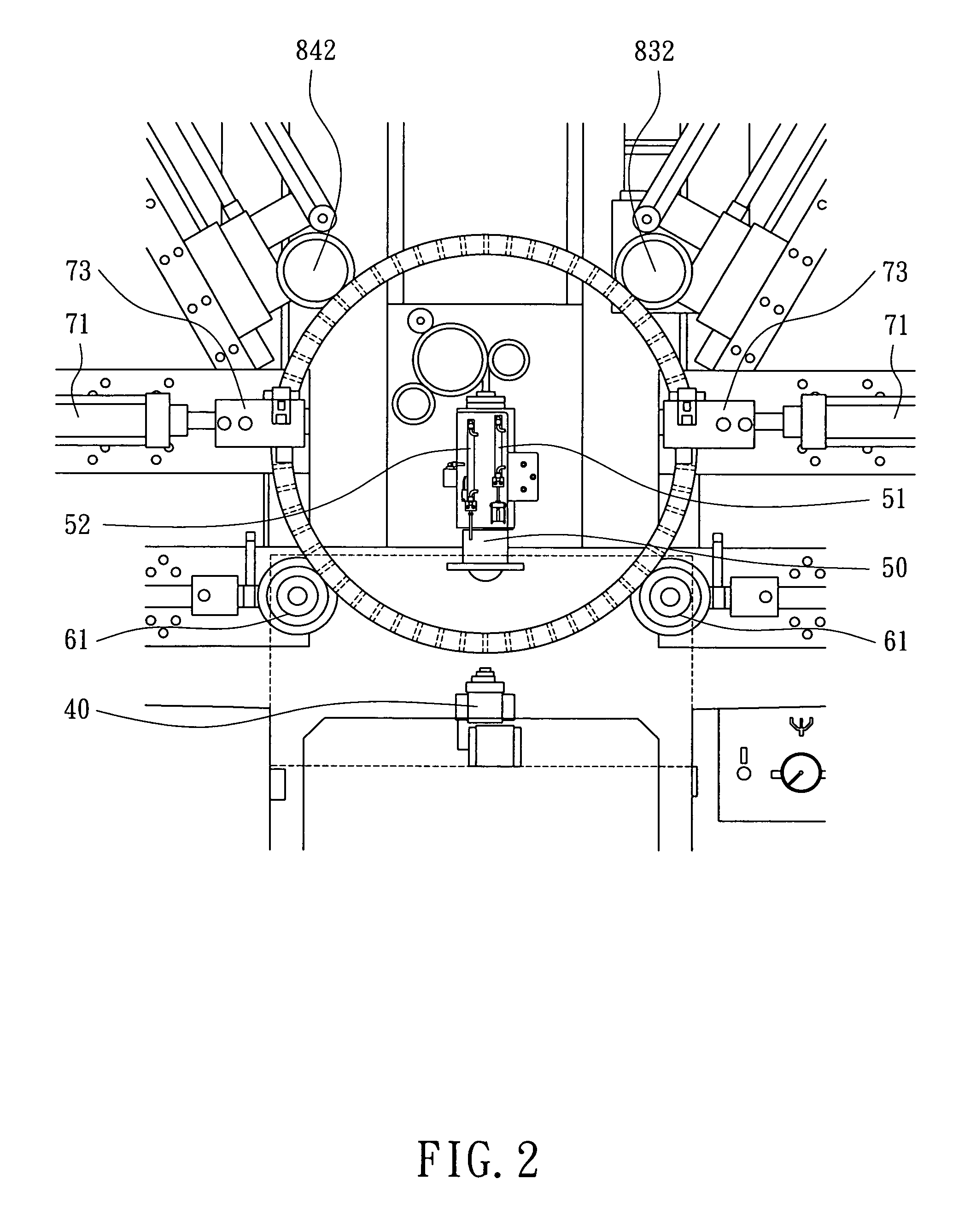
[0014]Referring to FIGS. 1 through 3, a hot-wire cutter includes a tank 10, a frame 20, a programmable control unit (not shown), a lower working head 40, an upper working head 50, a supporting unit 60, a restraining unit 70 and a rotating unit 80 according to the preferred embodiment of the present invention. The tank 10 is supported on the frame 20. The control unit is located in the frame 20. The lower working head 40 is located on the floor of the tank 10. The upper working head 50 is vertically movably supported on the frame 20. The supporting unit 60, the restraining unit 70 and the rotating unit 80 are located on the frame 20 in order. A line between the working heads 40 and 50 is in perpendicular to the floor of the tank 10. The working heads 40 and 50 and the units 70 and 80 are electrically connected to the programmable control unit.

[0015]The supporting unit 60 includes two circular beams 61 horizontally provided on the frame 20. The circular beams 61 support an annular wor...


PUM

PropertyMeasurementUnit
distanceaaaaaaaaaa
angleaaaaaaaaaa
anglesaaaaaaaaaa

Abstract

A hot-wire cutter includes a frame, a tank supported on the frame, a first working head located on a floor of the tank, a second working head movably supported on the frame, a supporting unit supported on the frame and used to support an annular work piece, a restraining unit supported on the frame and used to clamp the annular work piece, and a rotating unit supported on the frame and used to rotate the annular work piece. Thus, a line between the first and second working heads is directed through the centers of initial apertures in the annular work piece, one after another, to facilitate precise processing of sections of the annular work piece corresponding to the initial apertures.

Description

BACKGROUND OF INVENTION[0001]1. Field of Invention[0002]The present invention relates to a hot-wire cutter and, more particularly, to a hot-wire cutter for cutting an annular work piece.[0003]2. Related Prior Art[0004]A hot-wire cutter is an important machine tool for cutting metal work pieces precisely. A conventional hot-wire cutter includes a brass wire (or “hot wire”) inserted through a work piece. The brass wire discharges to the work piece so that are electric arcs between the brass wire and the work piece. Thus, like a wire saw, the brass wire cuts the work piece. Under the control of an NC program, the conventional hot-wire cutter moves the work piece. Thus, the conventional hot-wire cutter cuts the work piece into a shape according to the NC program with small errors.[0005]The conventional hot-wire cutter is controlled to move in XY / UV planes to find the centers of initial apertures, one after another, before the cutting under the control of the NC program is started. Howev...

Claims


Application Information

Patent Timeline
Patent Type & Authority Patents(United States)
IPC IPC(8): B23H1/00
CPCB26D5/32B26D7/06B26F3/12Y10T83/9292Y10T83/293
Inventor CHENG, SUNG-NENGLU, CHUNG-HSIENHSU, SHENG-CHIH
Owner EXCETEK TECH INC
Why Eureka
Try Eureka