
Precision Machining and Forming Modules for Micro Power Transmission Components

A technology of precision machining and forming molds, which is applied in the direction of household components, coatings, household appliances, etc., can solve the problems of low withstand voltage value of guide wire, short circuit of guide wire, easy deformation of guide wire plastic pressure, etc., so as to facilitate surface treatment and Effects of processing, ensuring relative position accuracy, and improving quality and precision

Active Publication Date: 2022-05-17
国网黑龙江省电力有限公司管理培训中心 +1
View PDF6 Cites 0 Cited by
  • Summary
  • Abstract
  • Description
  • Claims
  • Application Information

AI Technical Summary

Problems solved by technology

Destructive inspection was carried out on the original molded parts. The assembly positions of the brush accessories were designed in a staggered layout. Due to the structural design of the original brush components, the traditional mold design gate feeds from both sides of the lug, and the injection flow needs to repeatedly pass through the lug. , forming an S-shaped walking plastic pressure, the material flow continuously impacts the lugs during the filling process, the impact force makes the lugs tilt inside the injection molded part, and it is easy to cause a short circuit between the guide wires, or the withstand voltage between the guide wires is low. The passing rate of wear detection is low
Due to the low breakdown voltage resistance
[0003] For smaller and more delicate components, the diameter of the guide wire of the component accessories is 1 / 2 of the original size, and it is welded after bending and forming. Compared with the original component structure, there is no lug, and the spacing is dense, and the spacing is less than a quarter of the original , the distance dimension accuracy is high, the guide wire is easily deformed under plastic pressure, the size of the guide wire assembly molding part is about 1 / 2 of the original size, the volume is about 1 / 6 of the original size, and the parts are in a small molding space, high precision Intensive assembly requires tools such as a magnifying glass to assemble, which makes it difficult to install molds and assemble; when plastic pressing, due to the impact of the plastic pressure material flow on the guide wire, it is easy to cause deformation, displacement and short circuit of the guide wire, or cause excessive voltage resistance between the guide wires Low and breakdown, the traditional power transmission components and molds can not meet the pressure design requirements, resulting in the scrapping of the guide wire components and the low pass rate of finished products; due to the small and delicate components produced, the precision of the mold and the gating system requirements are relatively high High, in the narrow precision molding space, the precision assembly and positioning of the guide wire accessories need to test and innovate the mold structure according to the existing mold processing conditions. Therefore, it is necessary to improve the above problems

Method used


Image

  • Precision Machining and Forming Modules for Micro Power Transmission Components
  • Precision Machining and Forming Modules for Micro Power Transmission Components
  • Precision Machining and Forming Modules for Micro Power Transmission Components

Examples


Embodiment Construction

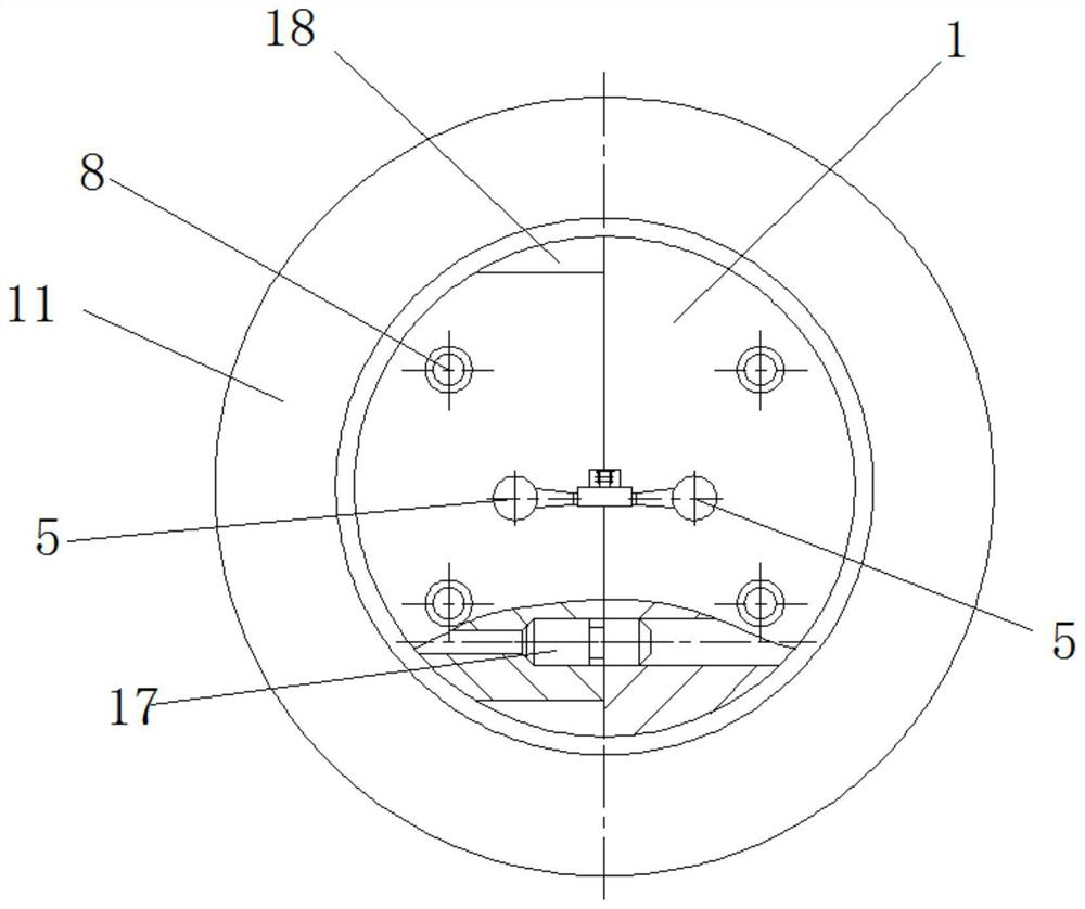
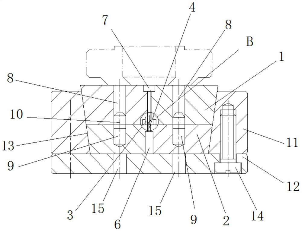
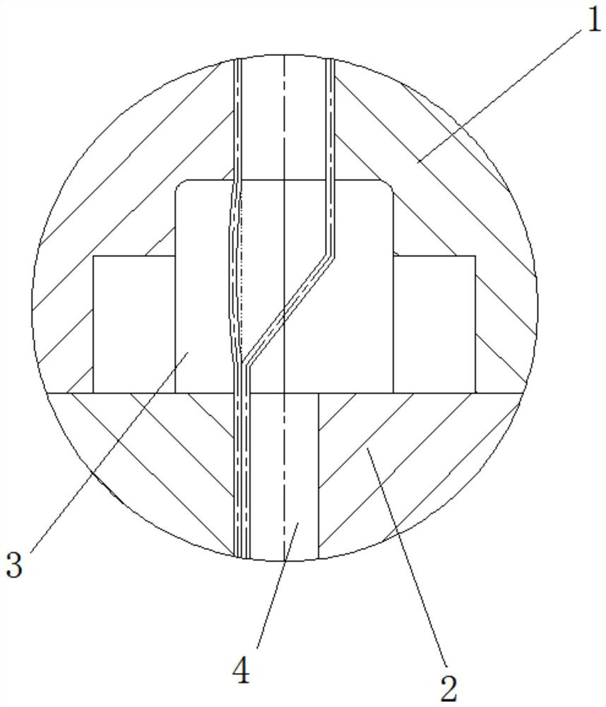
[0027] Attached below Figure 1-8 An embodiment of the present invention is described so as to clearly and completely describe the technical solution. Obviously, the described embodiment is only a part of the embodiments of the present invention, rather than all the embodiments.

[0028] In describing the present invention, it should be understood that the terms "upper", "lower", "front", "rear", "left", "right", "top", "bottom", "inner", " The orientation or positional relationship indicated by "outside", etc. is based on the orientation or positional relationship shown in the drawings, which is only for the convenience of describing the present invention and simplifying the description, rather than indicating or implying that the referred device or element must have a specific orientation, so as to Specific orientation configurations and operations, therefore, are not to be construed as limitations of the invention.

[0029] The precision machining molding module for micro-...


PUM


Abstract

Provides a precision machining molding module for micro power transmission components. A cavity is formed in the middle of the lower end surface of the upper half mold, and gates are formed on both sides of the upper end surface of the upper half mold, and the gate communicates with the lower end of the cavity through the runner. The middle part of the upper end surface of the lower half mold is equipped with a brush welding leg positioning groove corresponding to the position of the cavity, the lower half mold is equipped with a lower positioning device, and the middle part of the upper end surface of the upper half mold is equipped with The upper positioning device for positioning the upper end of the brush wire, the upper half mold and the lower half mold are positioned and assembled to form a tapered mold with a large upper part and a smaller lower part, and the upper and lower half molds pass through the clamping ring The device locks securely. The invention facilitates the assembly operation of the miniature power transmission components and the removal of plastic parts. The upper half mold and the lower half mold are precisely assembled with the micro power transmission components, and the positioning part adopts a completely open structure, which is convenient for processing, polishing and surface treatment, and improves the plasticity. Compression-molded Micro Power Transmission Components for quality and precision.

Description

technical field [0001] The invention belongs to the technical field of processing micro power transmission components, and in particular relates to a precision machining molding module for micro power transmission components. Background technique [0002] Micro-precision power transmission components are the core power transmission components of some equipment, and their processing and forming are realized by precision mold molding. In actual production, the molding process has been using the Soviet-style mold molding technology related to the 1950s. The old-fashioned component is equipped with three accessories. The structure of the accessory is to weld the guide wire on the lug. The lug is rigid enough and has good strength. Destructive inspection was carried out on the original molded parts. The assembly positions of the brush accessories were designed in a staggered layout. Due to the structural design of the original brush components, the traditional mold design gate f...

Claims


Application Information

Patent Timeline
Patent Type & Authority Patents(China)
IPC IPC(8): B29C45/14B29C45/64B29C45/27B29L31/34
CPCB29C45/14065B29C45/1418B29C45/14655B29C45/641B29C45/2708B29C45/14836B29C2045/14237B29C45/2606B29C2045/2709B29L2031/3406
Inventor 郭兰生
Owner 国网黑龙江省电力有限公司管理培训中心
Learn More