Utility vehicle
a technology for utility vehicles and vehicles, applied in the field of utility vehicles, can solve problems such as burdensome operation for passengers
- Summary
- Abstract
- Description
- Claims
- Application Information
AI Technical Summary
Benefits of technology
Problems solved by technology
Method used
Image

Examples
embodiment 1
(Embodiment 1)
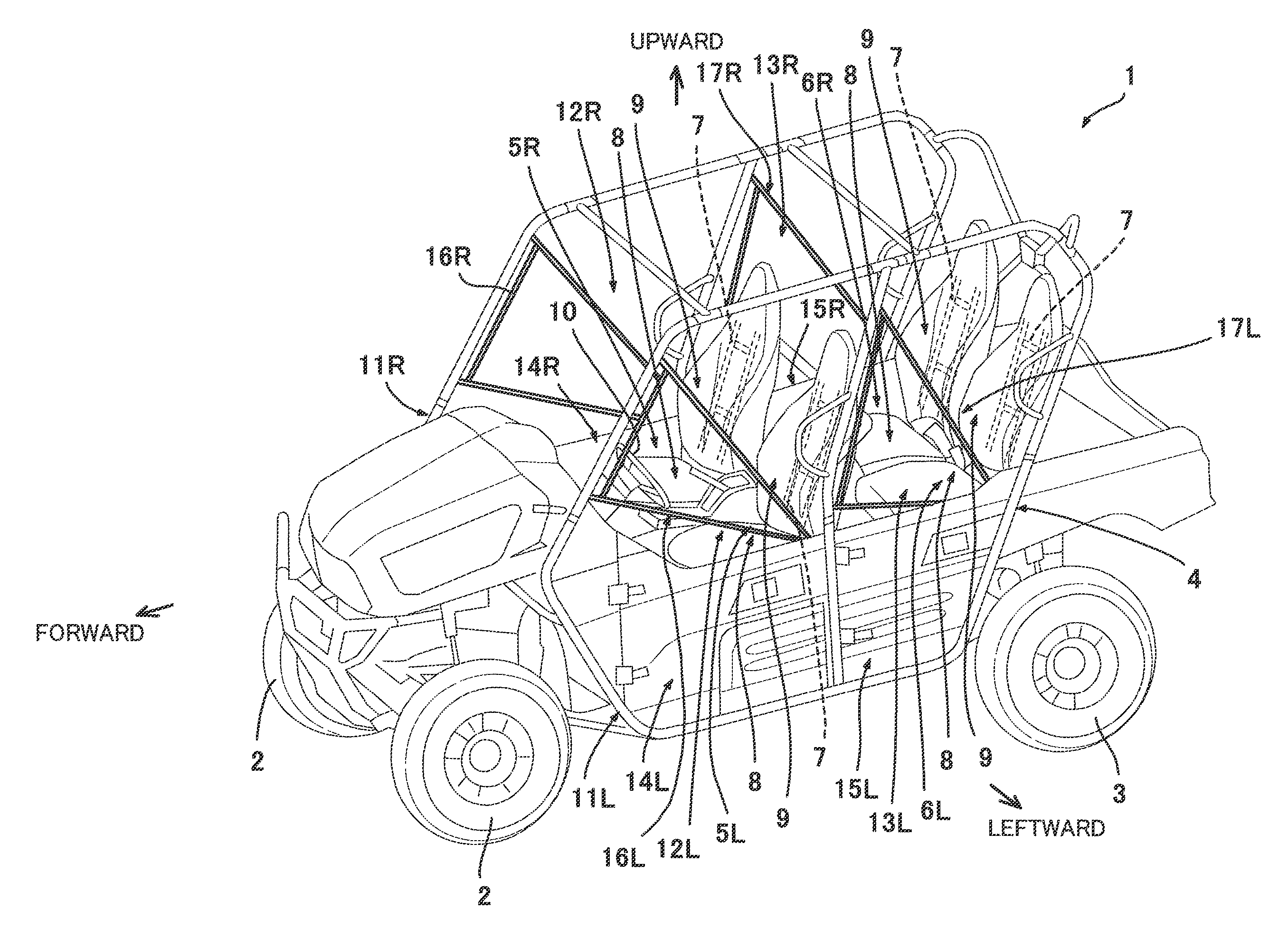
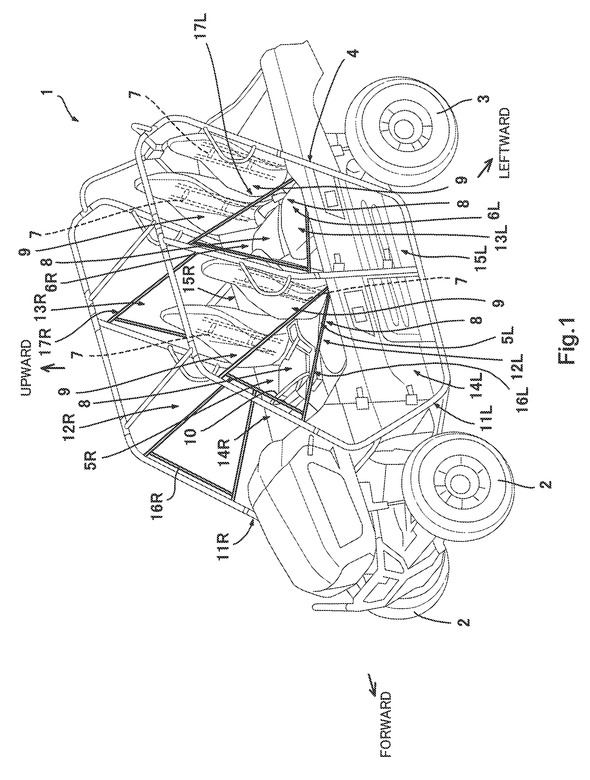
[0020]FIG. 1 is a perspective view showing an external appearance of a utility vehicle 1 according to Embodiment 1 of the present invention. As shown in FIG. 1, the utility vehicle 1 includes right and left front wheels 2, right and left rear wheels 3, a vehicle body frame 4 from which the four wheels 2 and 3 are suspended, and four seats 5L, 5R, 6L and 6R mounted to the vehicle body frame 4. Each of the four seats 5L, 5R, 6L and 6R includes a seat frame 7 (see FIG. 2) attached to the vehicle body frame 4, a seat bottom 8 mounted to the seat frame 7, and a seat backrest 9 mounted to the seat frame 7. A passenger can be seated on the seat bottom 8 and can be supported by the seat backrest 9. Among the four seats, two front seats 5L and 5R are arranged side by side in a rightward and leftward direction, while two rear seats 6L and 6R are arranged side by side in the rightward and leftward direction. The left front seat 5L is a driver seat and a steering wheel 10 is dispo...
embodiment 2
(Embodiment 2)
[0051]FIG. 8 is a side view showing the right side member 11R according to Embodiment 2 of the present invention when viewed from a right side. The right side member 11R shown in FIG. 8 has a structure identical to that shown in FIG. 4. In the embodiment, hinges 151 and a latch 152 of each of doors 114R and 115R are disposed at an opposite side of those of Embodiment 1. For this reason, locations of the protective covers 116R and 117R are different.
[0052]As shown in FIG. 8, the front door 114R is rotatably mounted at a rear portion thereof to a lower portion of the second pillar pipe element 42 via the hinges 151. The latch 152 is disposed at a front end portion of the front door 11R. The protective cover 116R has a triangular cover portion 161 for partially closing a region above an upper edge of the front door 114R, although its shape is slightly different from the shape in Embodiment 1. The protective cover 161 has a reinforcement band 162, a first mounting portion ...
modification example
(Modification Example)
[0055]FIG. 9 is a side view showing a door 214 according to a modification example of the embodiment of the present invention, when viewed from the left side. The door 214 shown in FIG. 9 is constructed of a substantially U-shaped metal-made pipe 215. The pipe 215 includes an upper pipe element 215a extending at left or right, a lower pipe element 215b extending at left or right, and a front pipe element 215c coupling a front end portion of the upper pipe element 215a to a front end portion of the lower pipe element 215b. A rear end portion of the upper pipe element 215a and a rear end portion of the lower pipe element 215b are rotatably mounted to the second pillar pipe element 42 via hinges 251. A protective cover 216 has a substantially trapezoid shape and is fastened to the pipe 215 to fill an inner region of the U-shaped pipe 215. A portion of the protective cover 216 protrudes in a triangular shape from an upper edge of the pipe 215. A mounting portion 27...
PUM
 Abstract
Description
Claims
Application Information
 - R&D
- Intellectual Property
- Life Sciences
- Materials
- Tech Scout
- Unparalleled Data Quality
- Higher Quality Content
- 60% Fewer Hallucinations
Browse by: Latest US Patents, China's latest patents, Technical Efficacy Thesaurus, Application Domain, Technology Topic, Popular Technical Reports.
© 2025 PatSnap. All rights reserved.Legal|Privacy policy|Modern Slavery Act Transparency Statement|Sitemap|About US| Contact US: help@patsnap.com