Electromagnetic wave measuring apparatus
a technology of electromagnetic wave and measuring apparatus, which is applied in the direction of instruments, antenna radiation diagrams, and clock signals. it can solve the problems of emi evaluation errors, complex superimposed fundamental waves and harmonics of a plurality of clock signals or digital transmission signals synchronized therewith, and difficulty in identifying a generation source of emi and a transmission path, so as to suppress the influence of electromagnetic waves
- Summary
- Abstract
- Description
- Claims
- Application Information
AI Technical Summary
Benefits of technology
Problems solved by technology
Method used
Image
Examples
first embodiment
(1. First Embodiment)
[0058](Use Example and Structure Example of Antenna Positioner)
[0059]First, a first embodiment of the present invention will be described with reference to FIGS. 1 to 15.
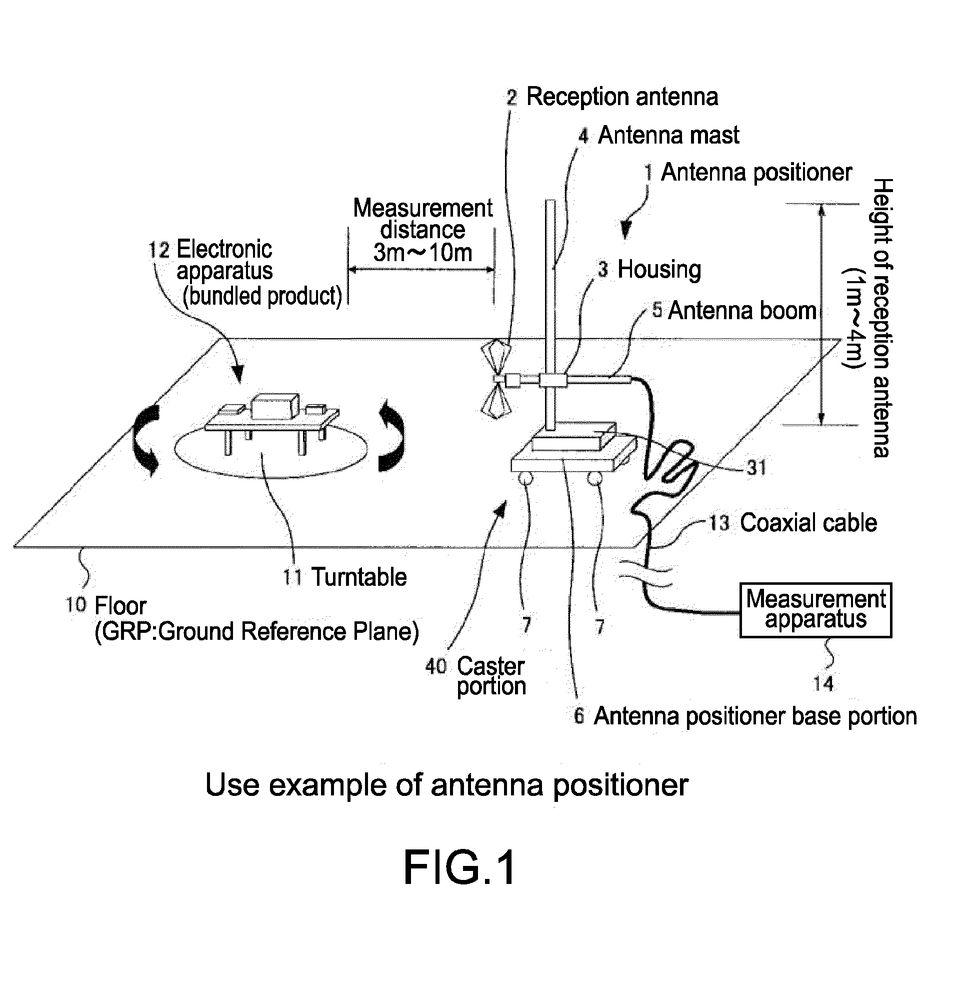
[0060]In this embodiment, there will be described an example in which the present invention is applied to an antenna positioner 1 as an electromagnetic wave measuring apparatus for measuring electro-magnetic interference (EMI) radiated from an electronic apparatus (bundled product) and the like. In this example, the electronic apparatus that is subjected to an EMI measurement and the antenna positioner 1 are placed within an EMI evaluation facility.
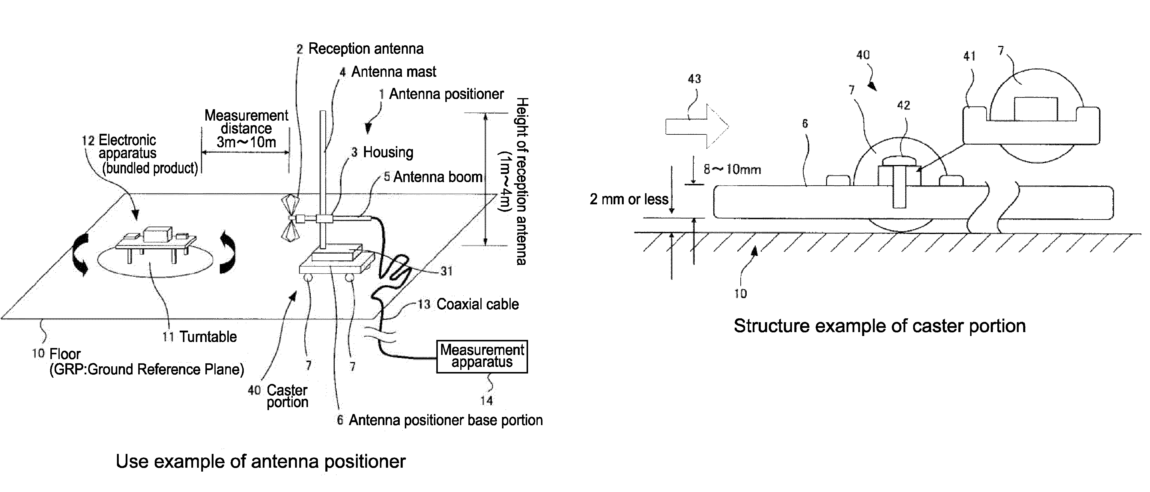
[0061]FIG. 1 shows a use example of the antenna positioner 1 of this example.
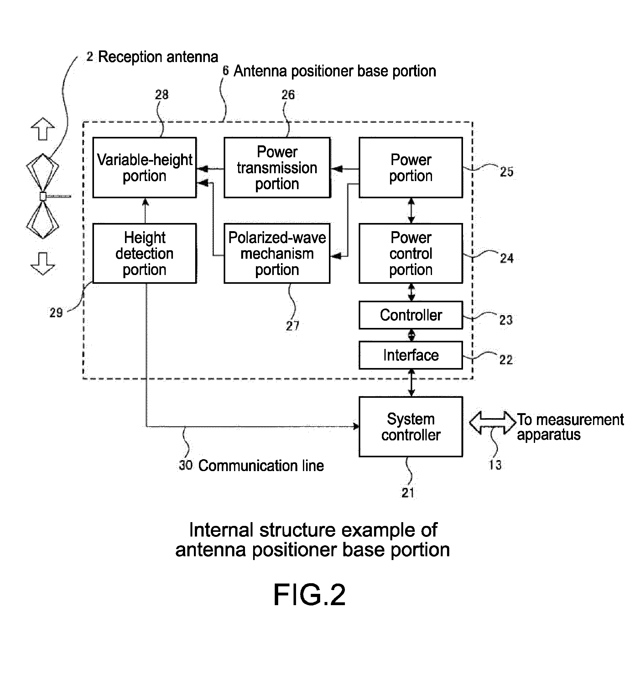
[0062]The antenna positioner 1 placed on a floor 10 called GRP includes a reception antenna 2 that measures an electromagnetic wave generated by an electronic apparatus 12 and an antenna mast 4 that holds the reception antenna 2 so as to be movable in a vertical direction. Th...
second embodiment
(2. Second Embodiment)
[0179](Thinning of Antenna Positioner Base Portion and Lowering of Center of Gravity Thereof)
[0180]Next, a second embodiment of the present invention will be described with reference to FIG. 16. In the following description, portions corresponding to the figures that has been described in first embodiment are denoted by the same reference numerals and detailed descriptions thereof will be omitted.
[0181]In this embodiment, there is examined a case where, when the flatness of the floor 10 near the position where the antenna positioner 1 is placed is insufficient, the separation distance therebetween is above 2 mm (for example, 5 mm). In this case, in accordance with a frequency band of EMI generated in the controller 23 and the power portion 25 such as a servo motor, a dielectric material having a largest dielectric constant in the frequency band is placed on a lower portion of the bottom surface of the antenna positioner base portion 6. At this time, a thickness...
third embodiment
(3. Third Embodiment)
[0186](EMI Suppression From Power Portion, Power Control Portion, and Controller)
[0187]Next, a third embodiment of the present invention will be described with reference to FIGS. 17 and 18. In the following description, portions corresponding to the figures that has been described in first embodiment are denoted by the same reference numerals and detailed descriptions thereof will be omitted.
[0188]FIG. 17 shows an external structure example of an antenna positioner base portion 80 when viewed from above.
[0189]A basic structure of the antenna positioner base portion 80 is similar to that of the antenna positioner base portion 6 described in the first embodiment above. The antenna positioner base portion 80 in this embodiment includes a frame 82 that reinforces a bottom surface steel plate 81 whose thickness is thin. By the frame 82, the strength of the antenna positioner base portion 80 is maintained and distortion deformation can be prevented. Further, the inter...
PUM
 Abstract
Description
Claims
Application Information
 - R&D
- Intellectual Property
- Life Sciences
- Materials
- Tech Scout
- Unparalleled Data Quality
- Higher Quality Content
- 60% Fewer Hallucinations
Browse by: Latest US Patents, China's latest patents, Technical Efficacy Thesaurus, Application Domain, Technology Topic, Popular Technical Reports.
© 2025 PatSnap. All rights reserved.Legal|Privacy policy|Modern Slavery Act Transparency Statement|Sitemap|About US| Contact US: help@patsnap.com


