Optofluidic microscope device with photosensor array

a technology of photosensor array and microscope device, which is applied in the direction of measurement device, scientific instruments, instruments, etc., can solve the problems of significant technical barriers, bulky optics of microscope design, and difficult miniaturization, and achieve significant economic benefits

Active Publication Date: 2012-11-20
CALIFORNIA INST OF TECH
View PDF42 Cites 35 Cited by
  • Summary
  • Abstract
  • Description
  • Claims
  • Application Information

AI Technical Summary

Benefits of technology

[0014]Embodiments of the present invention relate to techniques improving OFM devices. One technique which may be used eliminates the aperture layer covering the light detector layer. Other techniques retain the aperture layer, reversing the relative position of the light source and light detector such that light passes through the aperture layer before passing through the fluid channel to the light detector. Another technique adds an optical fiber bundle to relay light from light transmissive regions (such as apertures) to a remote light detector. This technique allows the light detector to be isolated from the light transmissive regions.
[0016]Other techniques add filters and / or use fluorescence to improve the capabilities of OFM devices. The above techniques, together with others specifically mentioned below, can be employed separately or in combination to improve the capabilities of OFM devices.
[0023]One embodiment is directed to an OFM device comprising a body defining a fluid channel having a longitudinal axis and an array of light detecting elements in the body. The array of light detecting element is configured to receive light from an illumination source through the fluid channel and generate data associated with the received light. The OFM device also comprises a first electrode and a second electrode at different locations along the longitudinal axis of the fluid channel. The first electrode and the second electrode are configured to generate an electrical field that moves an object through the fluid channel in a direction parallel to the longitudinal axis of the fluid channel while substantially preventing rotation of the object.

Problems solved by technology

These conventional microscope designs have bulky optics, and have proven to be expensive and difficult to miniaturize.
Some advances in optical microscopy promise to provide more compact systems but have presented significant technical barriers.
NSOMs are however restricted to detecting light in the near field.
Moreover, NSOMs have difficulty performing imaging at high throughput rates (i.e., high numbers of objects being imaged per unit time).
The resolution of the image is however limited by the pixel size of the light detecting elements of the light detector 11.
However, the resolution is limited in the y-direction by the size of each light detecting element (e.g., pixel size).

Method used


Image

  • Optofluidic microscope device with photosensor array
  • Optofluidic microscope device with photosensor array
  • Optofluidic microscope device with photosensor array

Examples


Embodiment Construction

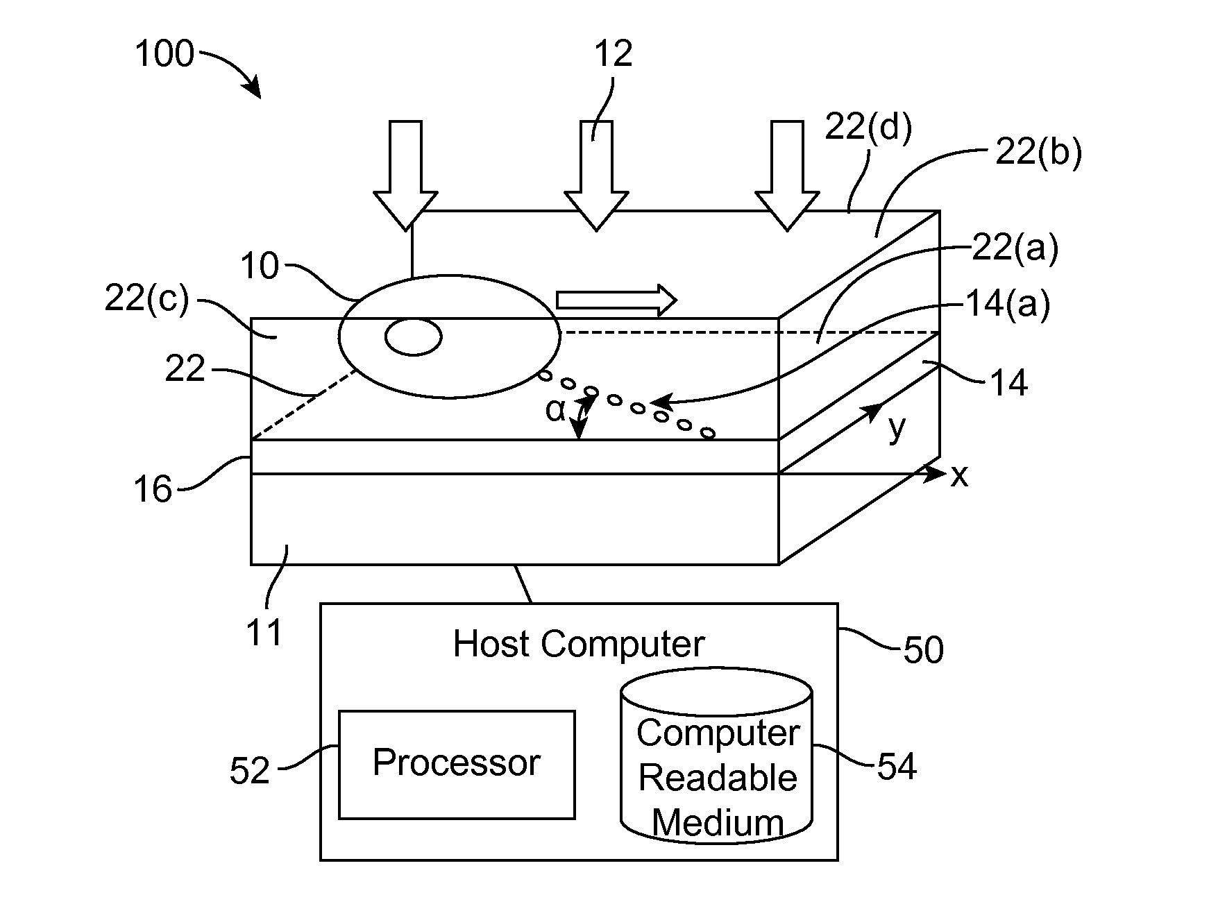
[0058]Embodiments of the present invention will be described below with reference to the accompanying drawings. One embodiment includes a technique for improving an OFM device by eliminating the aperture layer formerly located over the light detector layer. The OFM device of this embodiment has a body that defines a fluid channel having an upper surface and a lower surface. The body of the OFM device has a surface layer that coincides with the lower surface of the fluid channel. The illumination source is located above the upper surface of the fluid channel and provides light of suitable wavelengths onto an object (e.g., cell or micro-organism) travelling with a flow through the fluid channel.

[0059]An optical detector is in the surface layer of the body and receives light passing through the object from the illumination source and / or light re-emitted from fluorophores in the object. The optical detector includes individual light detecting elements (e.g., pixels) in the form of a one...


PUM

PropertyMeasurementUnit
sizeaaaaaaaaaa
heightaaaaaaaaaa
heightaaaaaaaaaa

Abstract

Embodiments of the present invention relate to techniques for improving optofluidic microscope (OFM) devices. One technique which may be used eliminates the aperture layer covering the light detector layer. Other techniques retain the aperture layer, reversing the relative position of the light source and light detector such that light passes through the aperture layer before passing through the fluid channel to the light detector. Another technique adds an optical tweezer for controlling the movement of objects moving through the fluid channel. Another technique adds an optical fiber bundle to relay light from light transmissive regions to a remote light detector. Another technique adds two electrodes at ends of the fluid channel to generate an electrical field capable of moving objects through the fluid channel while suppressing rotation. These techniques can be employed separately or in combination to improve the capabilities of OFM devices.

Description

STATEMENT AS TO RIGHTS TO INVENTIONS MADE UNDER FEDERALLY SPONSORED RESEARCH OR DEVELOPMENT[0001]The U.S. Government has certain rights in this invention pursuant to Grant No. EB005666 awarded by the National Institutes of Health and Grant No. HR0011-04-1-0032 awarded by DARPA.CROSS-REFERENCES TO RELATED APPLICATIONS[0002]This is a non-provisional patent application that claims the benefit of the filing date of U.S. Provisional Patent Application No. 61 / 068,131 entitled “Optofluidic Microscope” filed on Mar. 4, 2008. That provisional application is hereby incorporated by reference in its entirety for all purposes.[0003]This non-provisional application is related to the following co-pending and commonly-assigned patent applications, which are hereby incorporated by reference in their entirety for all purposes:[0004]U.S. patent application Ser. No. 11 / 125,718 entitled “Optofluidic Microscope Device” filed on May 9, 2005, now U.S. Pat. No. 7,773,227.[0005]U.S. patent application Ser. N...

Claims


Application Information

Patent Timeline
Patent Type & Authority Patents(United States)
IPC IPC(8): G01N21/00
CPCG01N21/53G01N21/6458
Inventor CUI, XIQUANHENG, XINLEE, LAP MANYANG, CHANGHUEI
Owner CALIFORNIA INST OF TECH
Why Eureka
Try Eureka